Advanced Sheet Metal Design Using NX Cad Challenge_7_ Metal bracket-II
Bracket 2
Objective:-
To design a Bracket-II in NX cad as per the given dimensions.
Introdiction:-
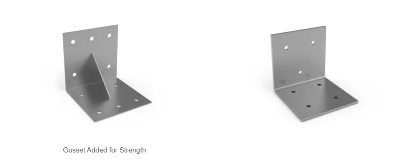
A bracket is an intermediate component for fixing one part to another. It is used to support the weight. Brackets vary widely in shape, here we are designing an L- shaped bracket. The shape and dimension of your bracket will be determined by the shape of the item it is holding up but will also be affected by the load capabilities and the ease in manufacturing. Keep in mind that strength considerations of metal bracket design are not just functions of the material thickness but of the bracket shape. As a metal part, adding specific features to the bracket can improve strength dramatically. Below are shown 2 metal part designs, both are of the same thickness but the first part will be significantly stronger due to the gusset (small triangular piece) welded on the bracket. This is a nice feature for keeping the profile of the bracket small yet creating a strong bracket.
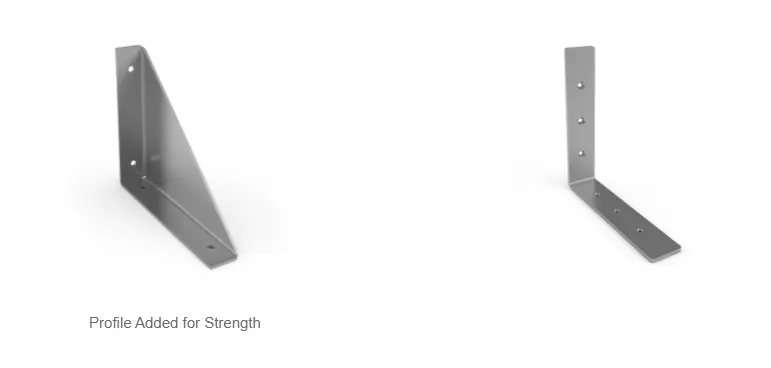
Another method to increase strength is to add more profile to the metal part. As you can see below the Pan Type bracket is significantly stronger than the same thickness L bracket because of the profile of the bracket.
Design Methodology:-
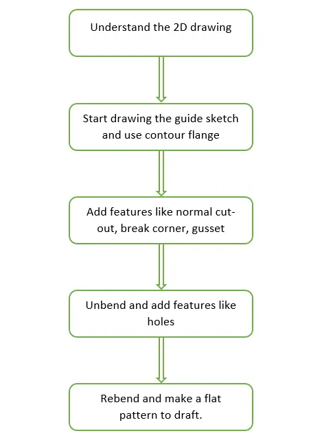
Sheet Metal Modeling:-
Features and tools:-
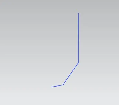
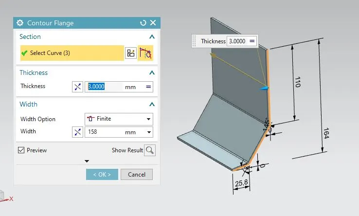
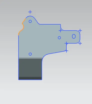
Contour Flange:
Creates a base feature by extruding the sketch along a vector or add material by sweeping the sketch along an edge.
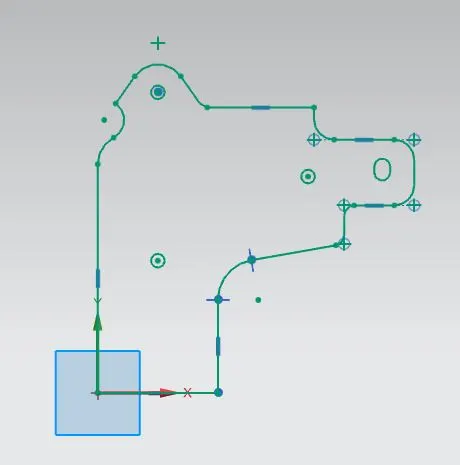
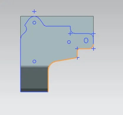
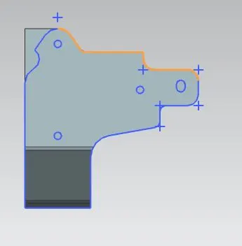
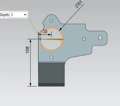
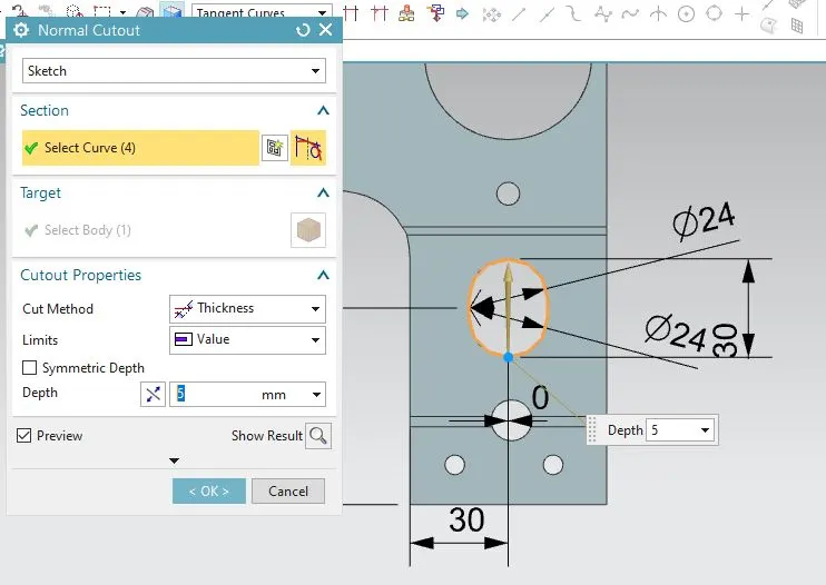
Normal Cut-Out:
It helps to cut material by projecting a sketch onto the model, cutting perpendicular to the face.
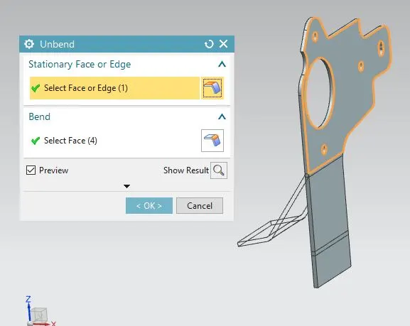
Unbend:
This feature helps to unbend the bent shapes to a flat pattern. In sheet metal the other features like cut-outs and holes needed to be created over the flat configuration. So that feature applied will be normal to a flat surface.
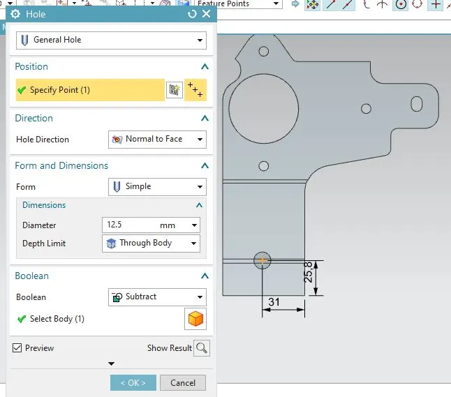
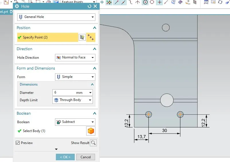
Hole:
Cut or remove the material with thread pattern on it. For applying the hole feature there should be a specific point, which will be the center of the hole.
Rebend:
This command helps to rebend the previously unbent sheet and have a component in its original form.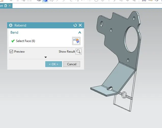
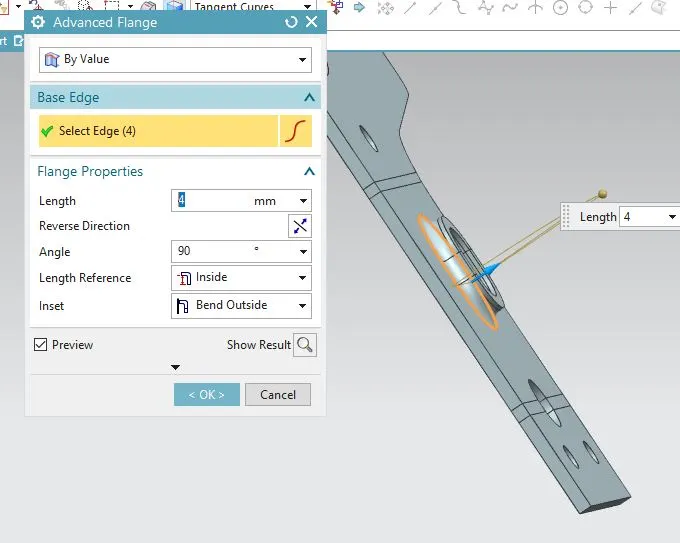
Advanced Flange:
Add a flange along an edge using a bend angle or a reference face. The edge and reference face can be curved.
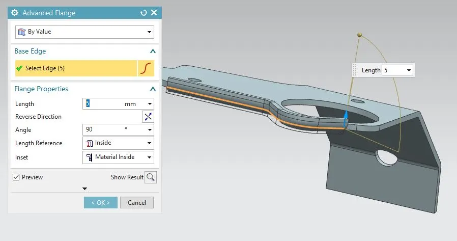
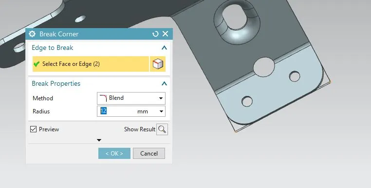
Break Corners:
This feature makes sharp edges to smooth round shape or to chamfer shape.
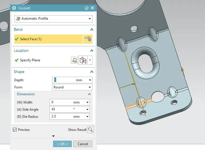
Gusset -
Use the Gusset command to create a stiffening feature on a part. You can:
- Create strengthening features where extra strength is required in the bend region.
- Create punched or embossed shapes in bend regions of sheet metal parts.
- Specify default dimensions for the Gusset feature using customer default
Isometric View:-
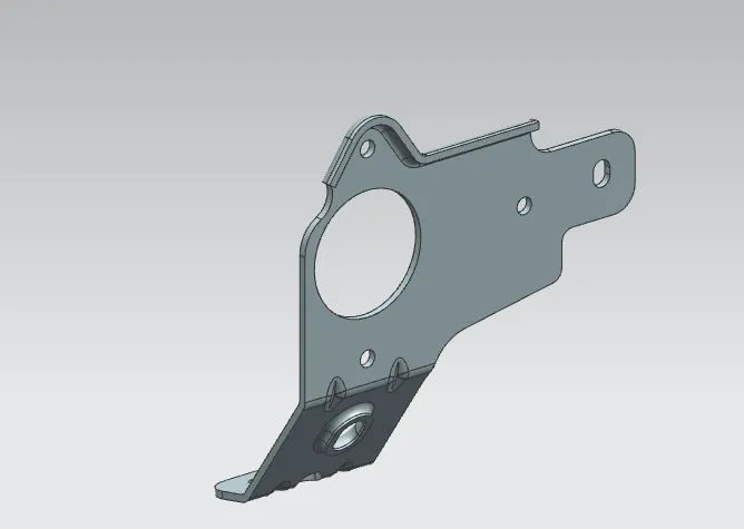
Top View:-
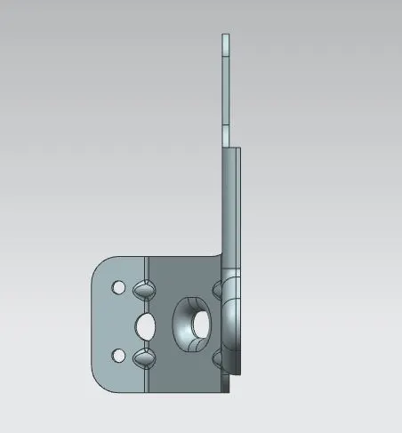
Front View:-
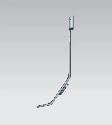
Side View:-
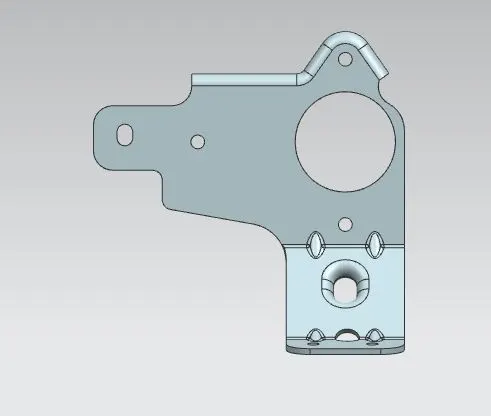
Cunclusion:-
By completing this challenge of design of metal bracket on the sheet metal application of Siemens NX, I've learnt how to analyse the given sketch and how to use different types of tools that are involved in completing this design like gusset, normal cutout, contour flange, advanced flange, hole, etc.