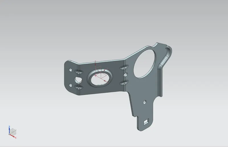
Advanced Sheet Metal Design Using NX Cad Challenge_7_ Metal bracket-II
REPORT
DESIGN 3D MODEL OF METAL BRACKET
OBJECTIVE: The objective of the project is to design and develop the Matel Bracket in sheet matel workbench by using NX CAD, and to understand the design methodology of sheet metal, features and commonds.
INTRODDUCTION:
The term “sheet metal” refers to any metal that can be formed into flat pieces of varying thicknesses. Thick metals are called plate. Metals used in the sheet metal industry include cold rolled steel, mild steel, stainless steel, tin, nickel, titanium, aluminum, brass, and copper.
There are six major types of sheet metal material, each with its own unique advantages:
- Alloy steel.
- Stainless steel.
- Carbon steel.
- Tool steel.
- Galvanized steel.
- Aluminum.
MUFACTURING PROCESS:
When making sheet metal, however, companies often use one or more of the following forming processes.
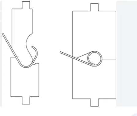
1) Curling:Curling is a sheet metal forming process used to form the edges into a hollow ring. Curling can be performed to eliminate sharp edges and increase the moment of inertia near the curled end. Other parts are curled to perform their primary function, such as door hinges.
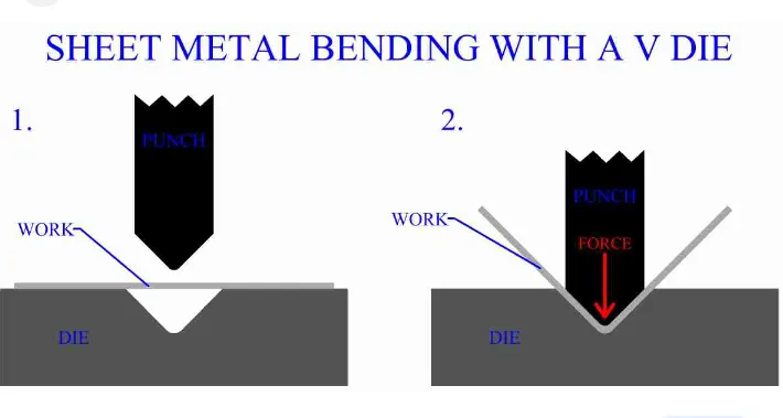
2) Bending:Metal bending is a process by which metal can be deformed when applying force to the subject, which causes it to bend at an angle and form the anticipated shape, which often results in it being in a 'V' or a 'U' shape. A press brake is a tool used in order to bend sheet metal and uses a punch and die to do this.
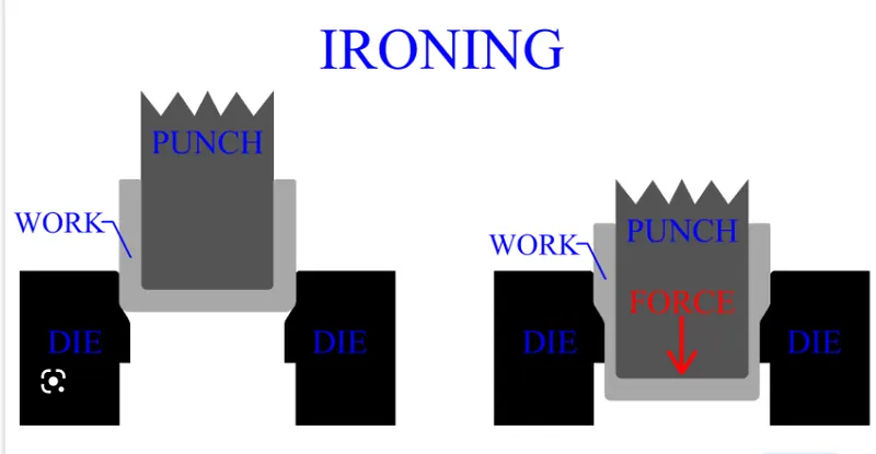
3) Ironing:Ironing can be accomplished during deep drawing or performed separately. The process uses a punch and die, forcing the metal sheet through a clearance that will act to uniformly reduce the entire thickness of the workpiece to a certain value. As with bending, the deformation does not reduce volume.
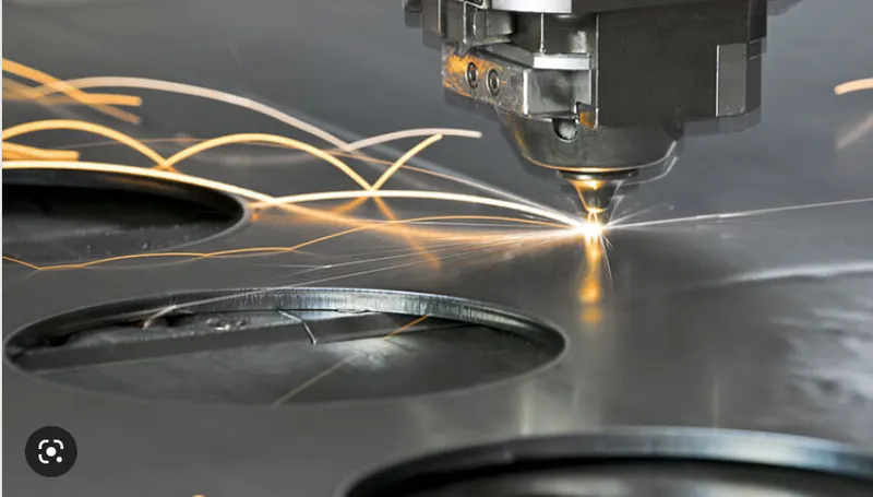
4) Laser Cutting:Laser cutting fabrication uses a high-power beam of light (laser) to cut out flat and thin sheets of metals. The process is directed by optics and computer numerical control (CNC) technology, which accounts for the high precision of laser cut parts.
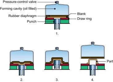
5) Hydroforming:Hydroforming (Sheet Hydroforming) is a specialized deep draw process that uses high-pressure rubber to shape and form metal workpieces. In sheet hydroforming, a metal sheet is placed over a die before highly pressurized water forces it down and makes it conform to the shape of the mold.
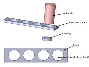
6) Punching:Metal punching is the process of impressing a form on a surface by pressure or percussion with a steel punch tool. In the metal punching process, the material is removed from a piece of sheet metal by applying a great enough cutting force. The metals that can be punched are different: steel, iron, copper, and aluminum.
DESIGN METHODOLOGY AND APPROACH:
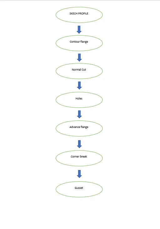
The below flow chat show the methodology or approach for this model:
COMMONDS USED FOR DEVELOPED THIS MODEL:
The following commands using while developing thsi model are listed below-
1) Contour Flange
2) Normal cut
3) Bend
4) Advance Flange
5) Unbend
6) Holes
7) Gusset
8) Corner break
1) Contour flange : Contour flange is use to creat the flange with complex or non-uniform profile in a very convinient way.
2) Normal cut: This is the command which help to remove the material as per the sketch profile, it is perpendicular to the sheet and it will follow the sheet metal shap.
3) Bend: This command help to bend the sheet at perticular place with given dimendions.
4) Advance Flange: This command creat the flanged as per required edge at specified dimension. In this also there will be different option to give relief.
5) Unbend: This command helps to the model to bring it in initial stage before bending witout loosing the bending operation, which help to achieved some cuts and holes or some specified patter, which is difficult to achieved in bend position.
6) Hole: This command helps to creat holes as per requirment. In this command variety of operation can be achieved.
8) Gusset: By using this command we can create gusset(stiffiner) between two face which is laying with some specifide angle. The gusset helps to give the strength to the component or model.
9) Corner Break:This command helps to giver the chamfer or fillet at given dimension for the smooth manufacturing operation.
ERROR IN THE MODEL:
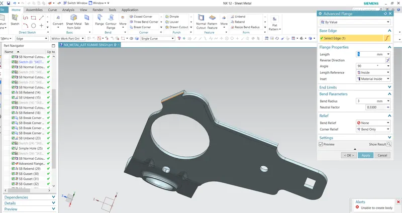
While creating of the flange by using Advance flange command getting error. The flange is not continue and its getting breake at some edges. I tried with diffirent way by reducing flange length, radius size, tengent curve single curve, non relief option etc. but its getting same error. For the reference i have attached the screen shot below.
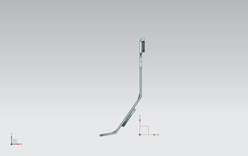
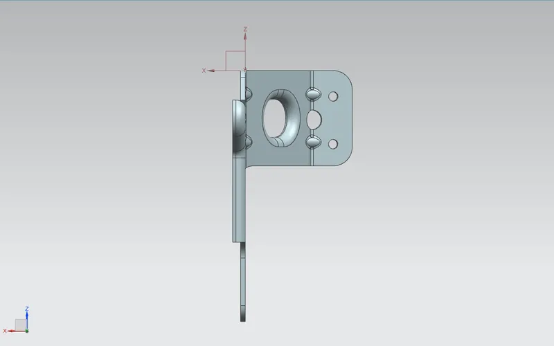
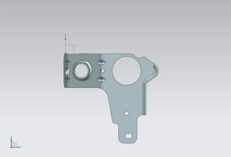
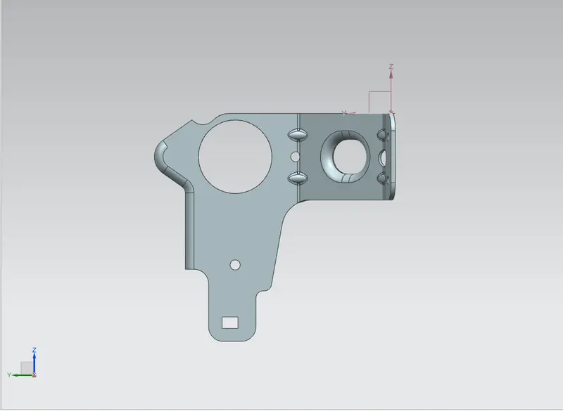
DIFFERENT VIEW OF MODEL:
CONCLUSION:
In this project we learn the commands and proccedure for designing the sheet metal , and learn how to execute the commands. While design of sheet metal model we need to define the proper dimension and need to give proper relief and remove all the sharp edges for smooth operation.
In this model we get some error while doing advane flange operation. We try to resolved with different trail but not getting resovle.