Design Metal Bracket
AIM:- To design a Metal Bracket using the various features available in the NX Cad.
INTRODUCTION:-
NX cad is a designing software that is primarily concerned with the sheet metal designing. The tools and features available are unlike other softwares such as SOLID-WORKS or CREO. The tools are specific enough to make sheet metal designing easier. Given the fact that manufacturing a proper component is key in the mechanical industry also the fact that using sheet metal for complex designing is tough & this software comes in handy to overcome the difficulties and helps us visualise how the component is going to look for a manufacturer. Features such as Unbend and drafting goes a long way when it comes to understanding the component.
The Bracket is a sheet metal component that is achieved by the contour flange feature. Which then under goes various details such as normal cutout, Advanced flange, gusset and etc. These details help to fill the life out of the sheet metal and brings out the bracket that we know.
Metal Bracket:- Metal Bracket is a device that projects from or overhangs a wall to carry a weight. It may also serve as a ledge to support a statue, the spring of an arch, a beam, or a shelf. The metal brackets are manufactured by conducting stamping or die casting operation.
Applications of Metal Brackets:
- Bracket for split Air conditioners
- LED television mount bracket
- Cable crimp sleeve brackets in Automobiles
- Hinge Brackets for doors
DESIGN METHODOLOGY:-
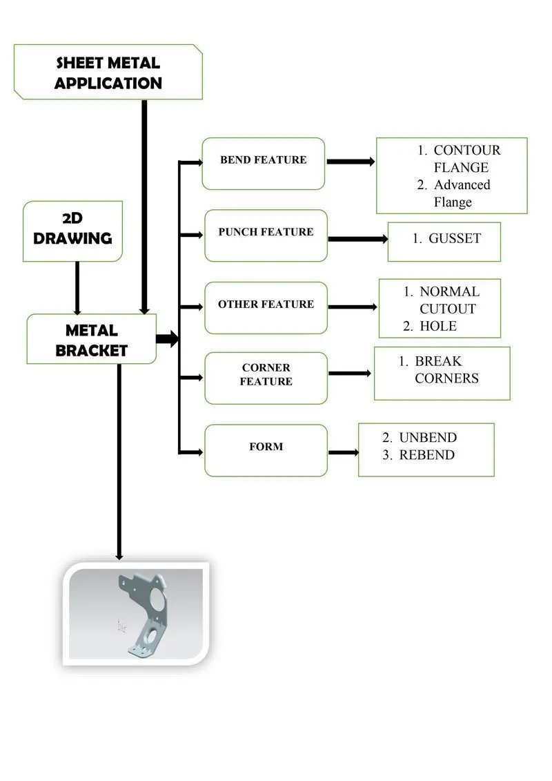
DESCRIPTION:-
SKETCH: Adds curves, dimensions and constraints to a plane or face. Eg: Sketch about the YZ plane of a combination of lines and arcs to create a flange.
CONTOUR FLANGE: Creates a base feature by extruding a sketch along a vector, or adds the material by sweeping a sketch along an edge or chain of edges. Eg: The flange created by the sketch about the plane.
NORMAL CUTOUT: Cuts material by projecting a sketch onto the model and then cutting perpendicular to the faces intersected by the projection. Eg: To cut different sketch details on the bracket.
BREAK CORNER: Rounds or chamfers a sharp corner of a tab or flange. Eg: Applied to the corners of the flange.
UNBEND: Flattens a bend and the material adjacent to the bend. Eg: To make the flange into a flat sheet.
REBEND : Restores an unbend feature to its previous bent state, along with any features added after the unbend feature. Eg: To bring back the bracket to its orginal state.
ADVANCED FLANGE: Adds a flange along a edge using a bend angle or a reference face. The edge and reference face can be curved. Eg: Appliied to the tanget relationed curves and lines on the top of the bracket.
HOLE: Adds a hole to one or more soild bodies in a part or assembly with options for counterbored, countersunk, and threaded. Eg: Holes on the surface that replicate natural holes.
GUSSET: Creates a stiffening gusset on the part. Eg: Gusset on the bent surface created due to the flange.
SCREENSHOTS:-
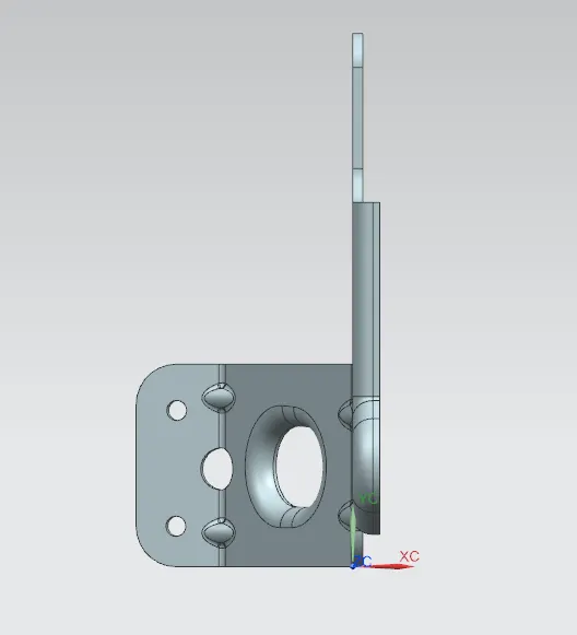
TOP VIEW:
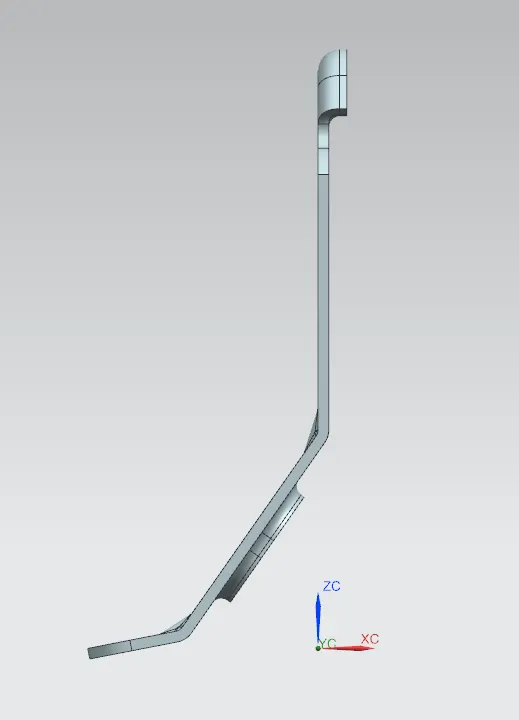
FRONT VIEW:
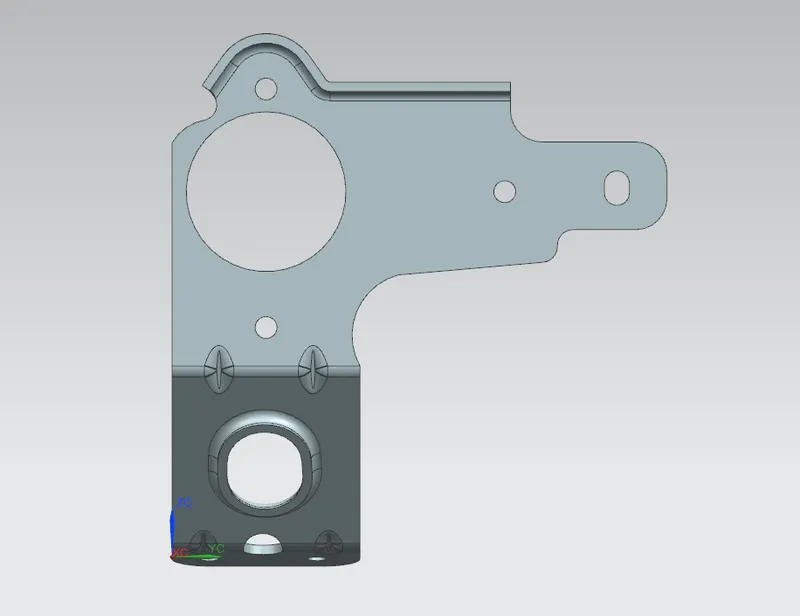
SIDE VIEW:
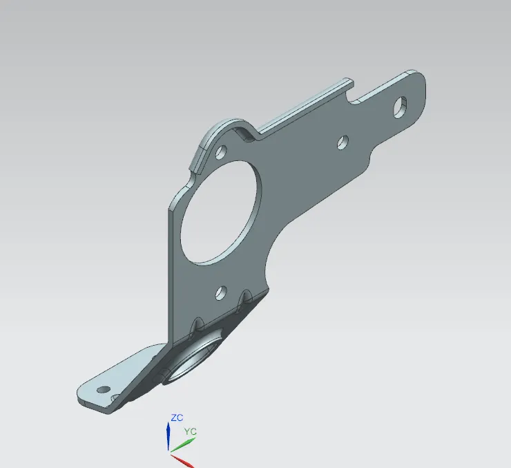
ISOMETRIC VIEW:
CONCLUSION:-
The design of Metal Bracket using various features and tools in NX CAD was successfull.