Advanced Sheet Metal Design Using NX Cad Challenge_7_ Metal bracket-II
AIM:
To designed a sheetmeal componnet of metal bracket using NX Cad and explain in detail report
INTRODUCTION:
Sheet metal fabrication includes important design considerations to help improve part manufacturability, enhance cosmetic appearance and reduce overall production time.
Sheet metal fabrication is the process of forming parts from metal sheet by punching, cutting, stamping and bending.
3D CAD files are converted into machine code, which controls a machine to precisely cut and form the sheets into the final part.
Sheet metal parts are known for their durability, which makes them great for end use application. Parts used for low volume prototypes and high volume production runs are most cost effective due to large initial setup and material costs.
Because parts are formed from a single sheet of metal, designs must maintain a uniform thickness. We have to be sure to follow the design requirements and tolerances to ensure parts fall closer to design intent and cutting sheets of metal.
DESIGN METHODOLOGY:
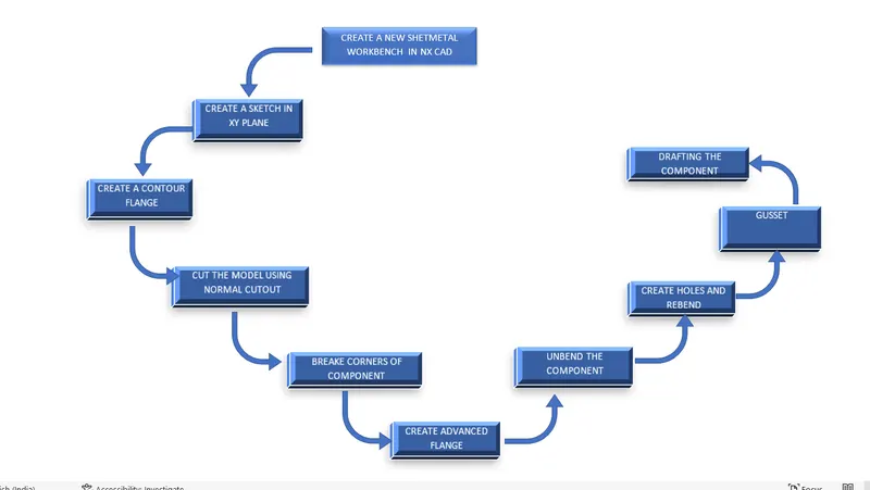
TOOLS AND FEATURES USED TO DESIGN METAL BRACKET:
SKECTH:
Sketch creates the 2D drawing for which the model is to be designed.It consists of several sketch tools like line arc,rectangle, spline etc.
CONTOUR FLANGE:
It is used for extruding the sketch along the defined vector direction for non linear profiles.It consists of base as well as secondary cotour flanges.
NORMAL CUTOUT:
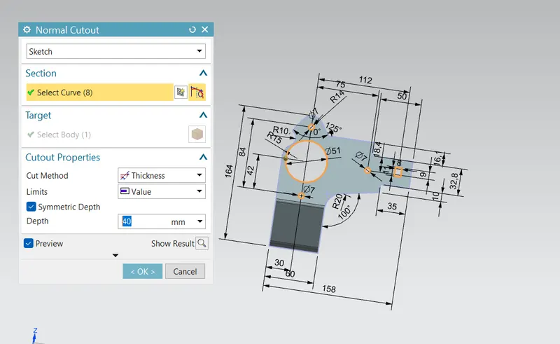
It is used for removing the material by projecting sketch onto the model and then cutting perpendicular to the faces intersected by the projection.
BREAK CORNER:
This feature is used for creating smooth faces at the edges in order to avoid Sharp edges.
UNBEND:
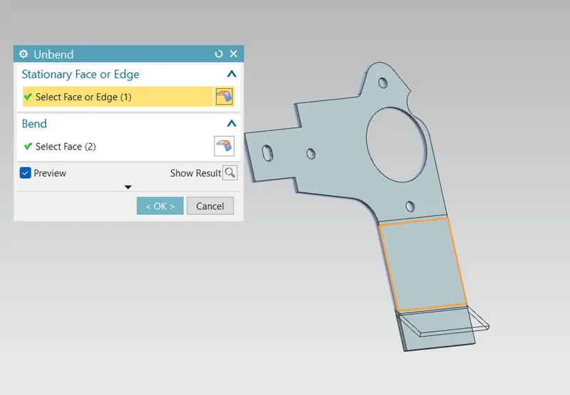
Unbend feature converts the formed bended sheet metal into flat sheet metal by using one of the stationary face as flat face.
REBEND:
Rebend is used to revert the flat sheet metal into bended form.
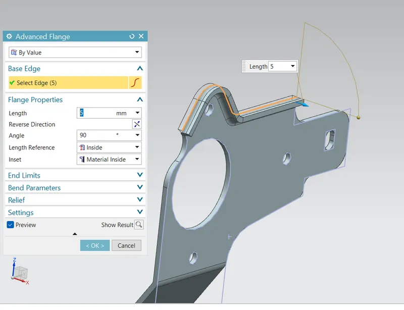
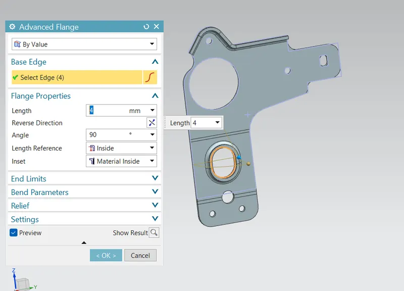
ADVANCED FLANGE:
This is the advanced feature in sheet metal features and it is as similar to normal flange.Normal flange will extend the material along the straight edge where as advanced flange extend the material along the tangential edges.
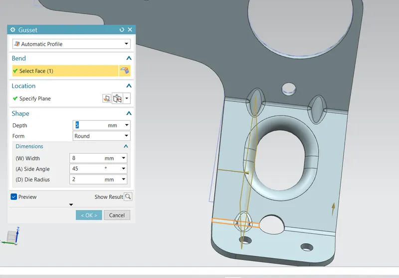
GUSSET:
Gusset is the stiffening feature which is mainly used for providing additional strength to the sheet metal.Gusset can be applied on the bend faces along specified plane direction.
MODELLING PROCEDURES:
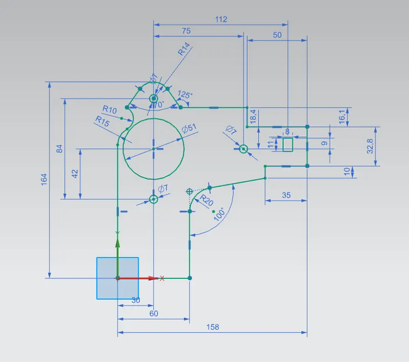
SKETCH CREATION:
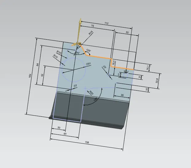
Create the new sketch on YZ plane(Right plane) and draw the profile as per dimensions as shown.
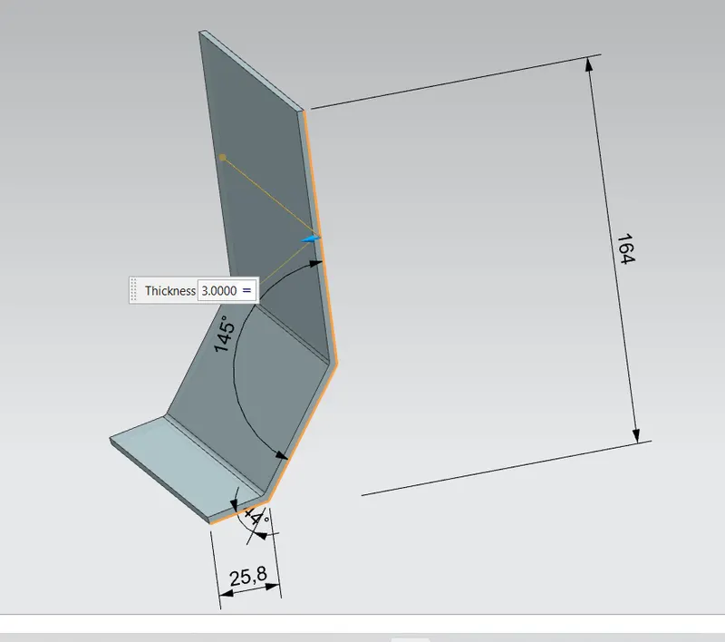
COUNTOUR FLANGE
Create new sketch on XZ plane(Front plane) and draw the profile per dimensions shown below.
Create contour flange by selecting sketch2 as section curve
Change thickness to 3mm and width as 158mm.
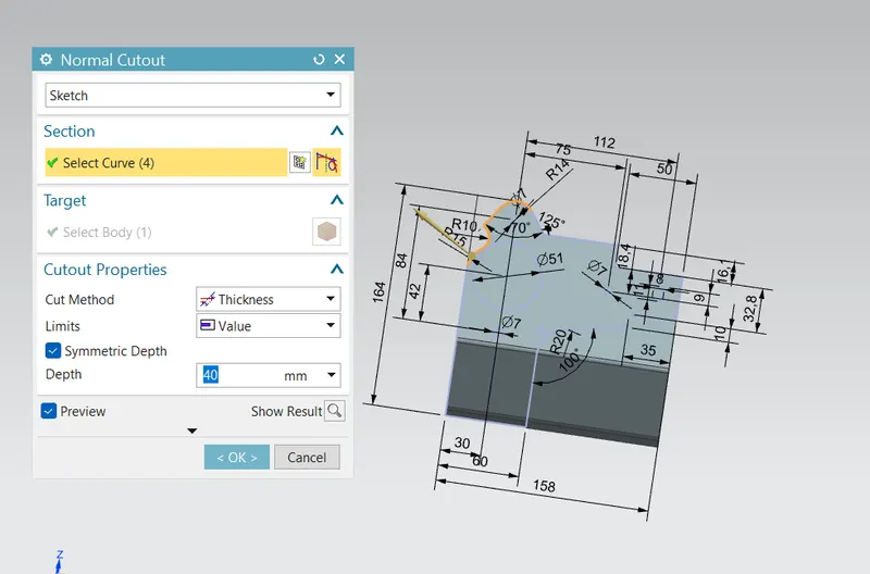
NORMAL CUTOUT
With reference to 2nd sketch create a counter flange and with reference to 1st sketch trim(eliminate) the unwanted portion from using normal cut option
UNBEND:
Unbend the bracket.
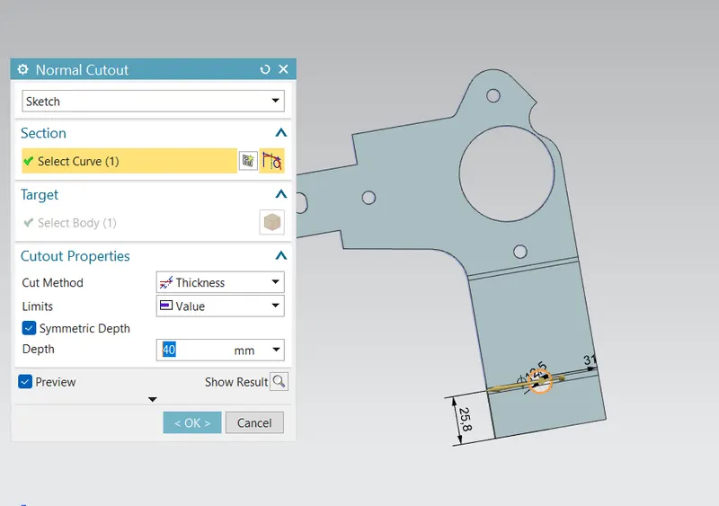
Sketch a circle and cut the portion using normal cut option and rebend the bracket.
BREAK CORNER
Use break corner option to make round corners
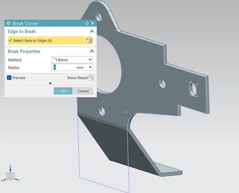
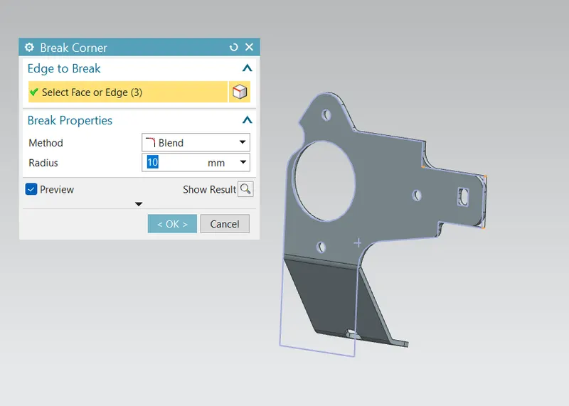
REBEND:
Rebend the bended surface.
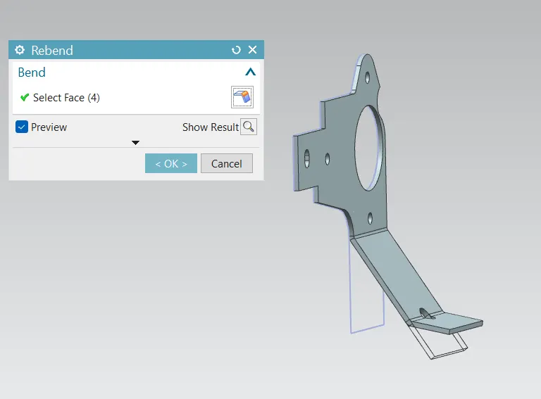
ADVANCED FLANGE:
Click on the advanced flange option and select the top edge as shown the picture and unbend the bracket.
HOLE
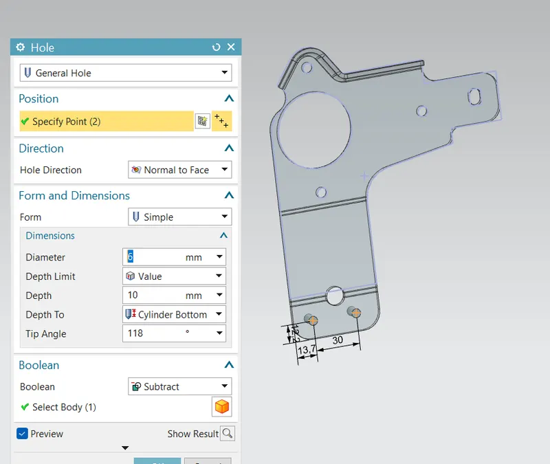
- Open the hole feature and by using the sketch creation,create the two points with required dimensions as shown.
- Exit from sketch and then holes are generated at positioned points.
- Change the hole diameter to 6mm.
GUSSET:
Apply the gusset on the bend face with distance -15mm from the selected face and again do the same steps for the another three gussets.
ISOMETRIC VIEW
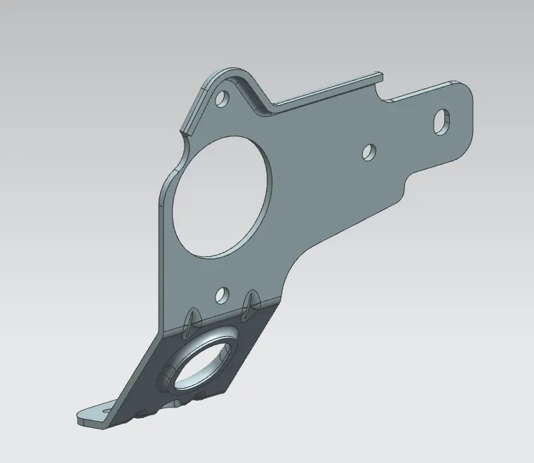
FR0NT VIEW
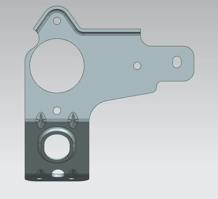
BACK VIEW
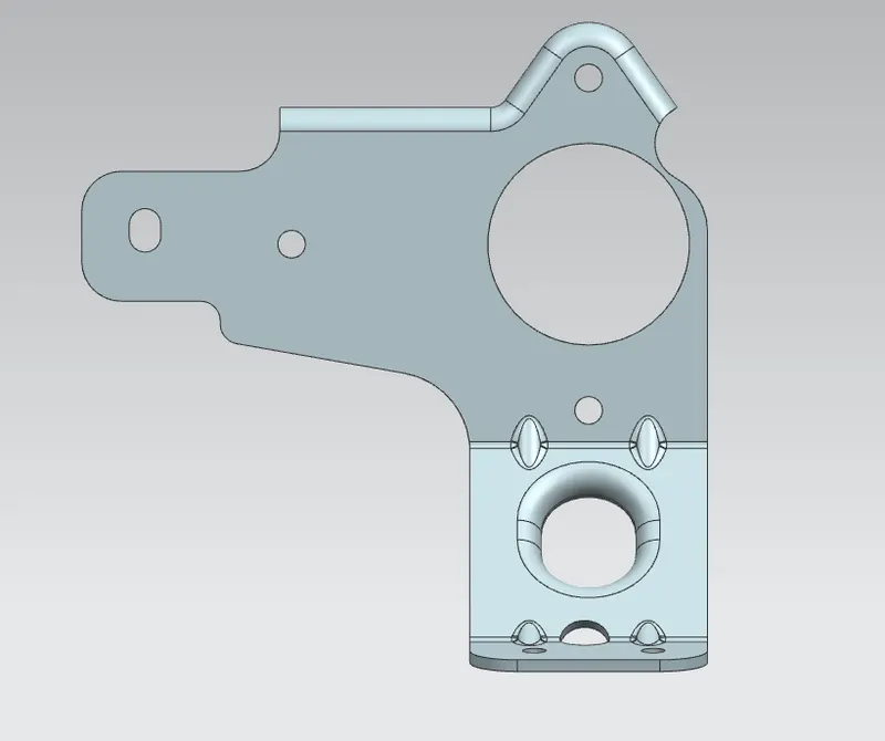
LEFT SIDE VIEW
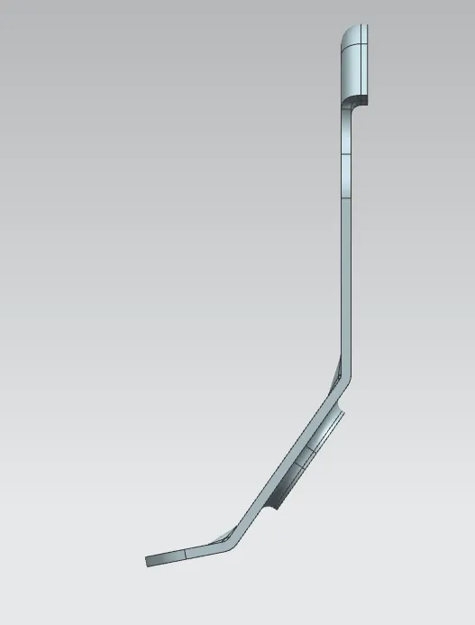
RIGHT SIDE VIEW
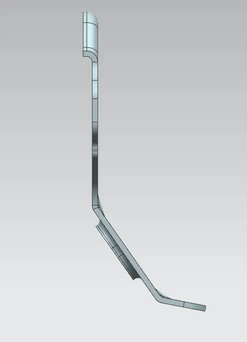
TOP VIEW
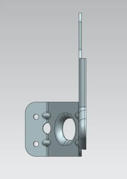
BOTTOM VIEW
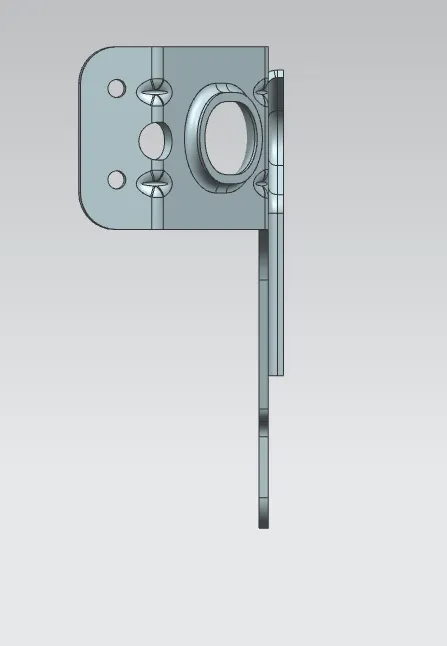
DRAFTING:
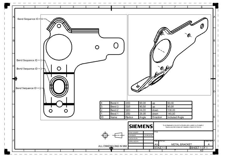
After that select the drafting ribbon from the application tab.
Automatically it opens the sheet dialogue box and select sheet size as per requirement.
Select base view tab feature and select flat pattern as model view.
Select the suitable scaling ratio based on the model view.
CONCLUSION:
Design of sheet metal bracket-II can be completed by using several normal features along with the advanced feature like advanced flange from the sheet metal workbench within the NX-CAD software.