Advanced Sheet Metal Design Using NX Cad Challenge_7_ Metal bracket-II
METAL BRACKET
Objective: To design and create the given sheet metal component "Metal Bracket" with given dimensions using the various commands in the Siemens NX CAD software.
Introduction:
- The given sheet metal component is an example and for understanding purpose of various tools and features in sheet metal workbench and for practice.
Design methodology:
1. Sketching the shape
2. Construction of base features
3. Creating additional features
4. Unbend and punch features/cutouts
5. Creating flat pattern
6. Draft Analysis
Tools/Features used:
1. Sketch: It creates a sketch in the current application. Use the direct sketch tools to add curves, dimensions, constraints, etc.
2. Circle: This feature creates a circle through three points or by specifying its center and diameter.
3. Profile: It creates a series of connected lines as well as arcs in string mode, that is, the end of the last curve becomes the beginning of the next curve.
4. Contour Flange: It creates a base feature by extruding a sketch along a vector, or adds material by sweeping a sketch along an edge or chain of edges.
5.Normal Cutout: This tool cuts the material by projecting a sketch onto the model and then cutting perpendicular to the faces intersected by the projection.
6. Break Corner: This tool rounds or chamfers a sharp corner of a tab or flange.
7. Unbend: This tool flattens a bend and the material adjacent to the bend.
8. Rebend: It restores an unbend feature to its previous bent state, along with any features added after the unbend feature.
9. Advanced Flange: It adds a flange along an edge using a bend angle or a reference face. The edge and reference face can be curved.
10. Hole: It adds a hole to one or more solid bodies in a part or assembly with options for counterbored, countersunk and threaded.
11. Gusset: This feature creates a stiffening gusset on the part.
12. Drafting: This feature starts the drafting application, which provides tools to create and maintain drawings of the design model.
Model Views:
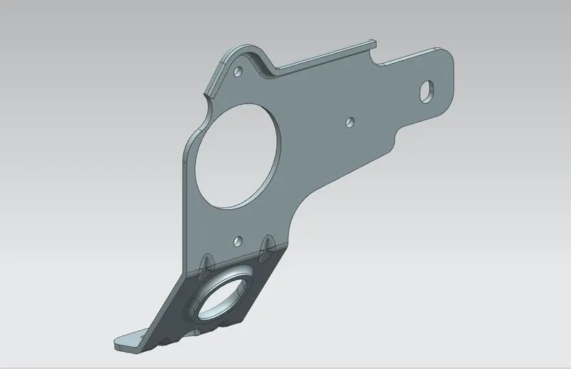
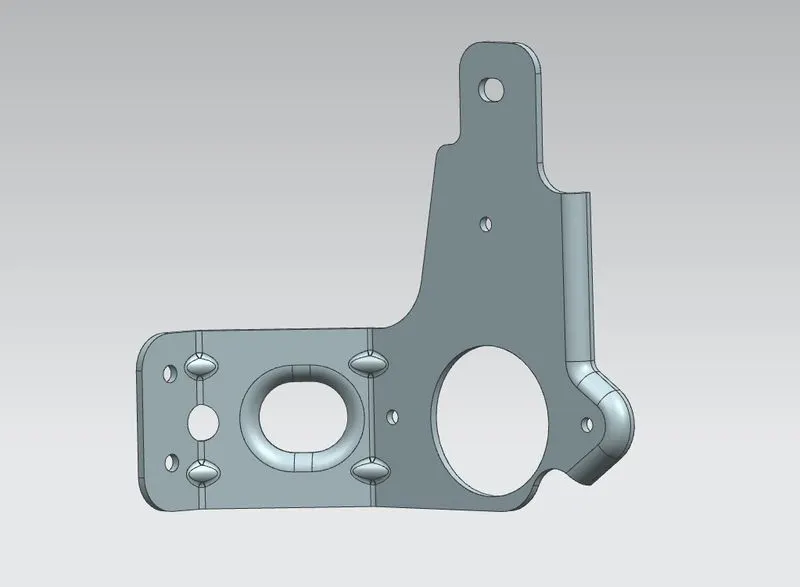
Trimetric view Top view
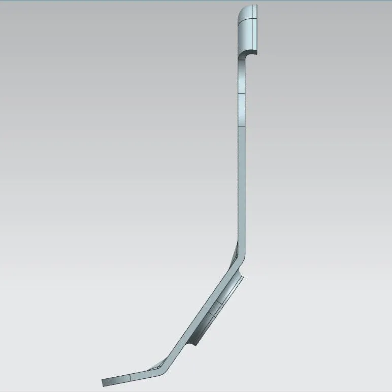
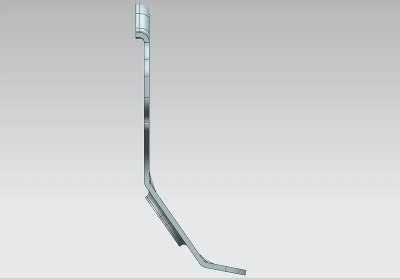
Front view Back view
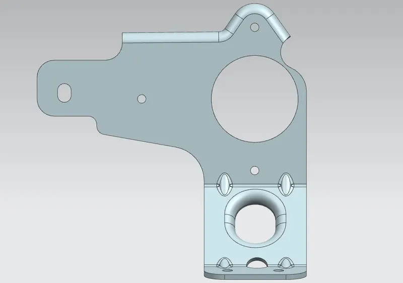
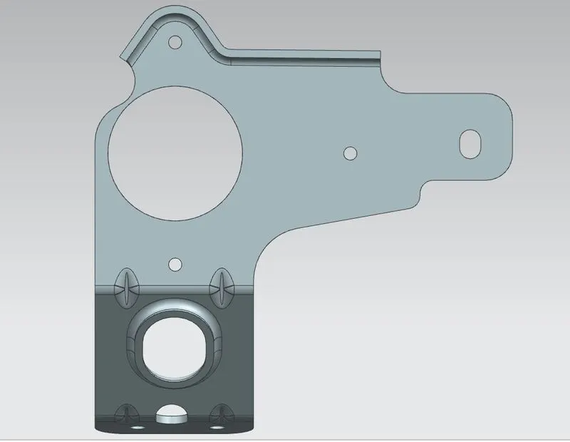
Left view Right view
Draft/Drawing sheet:
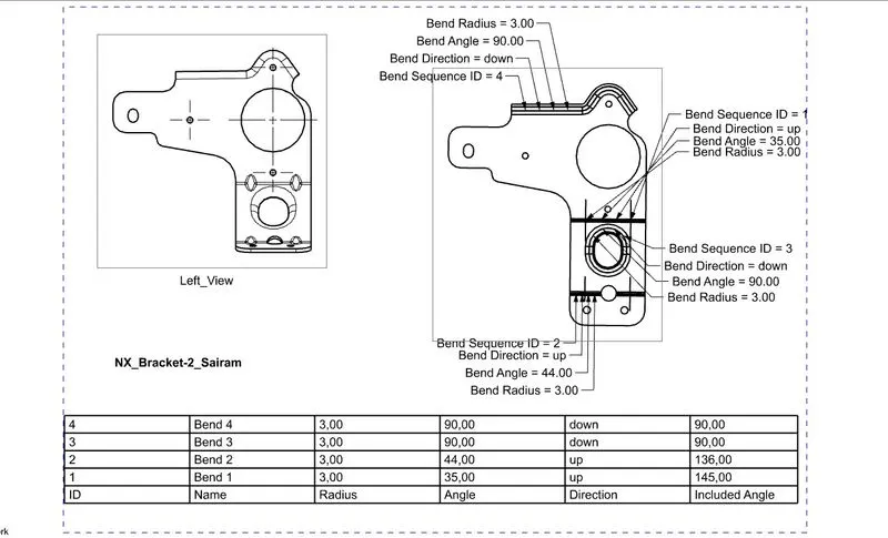
Conclusion: So the given sheet metal component "Metal Bracket" is designed and draft analysis is done as per the given dimensions using Siemens NX CAD software and the final results are shown above.