Advanced Sheet Metal Design Using NX Cad Challenge_7_ Metal bracket-II
Designing of Metal Bracket Using NX CAD
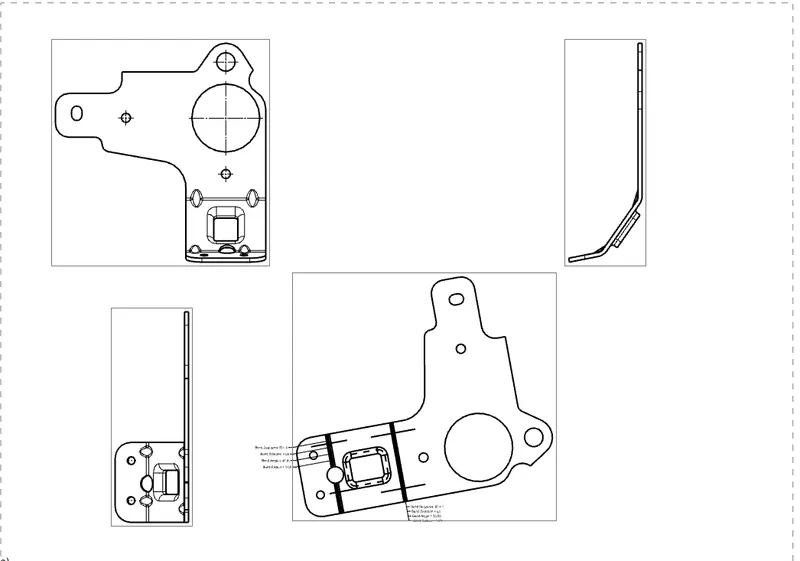
Objective: To design a sheet metal Bracket from a 2D sketch with help of NX CAD tool features.
Introduction:
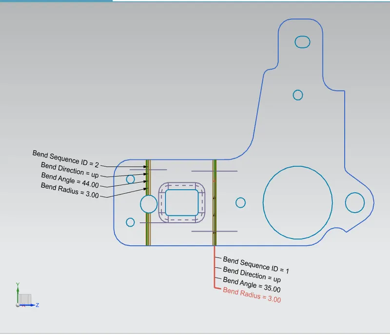
In this project convert the2D sketch to 3D and add the advanced features to get strengthen the bent portions.
For this project, I have chosen the NX tool with help of advanced sheet metal design features.
Methodology:
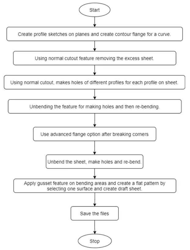
Description: Features used
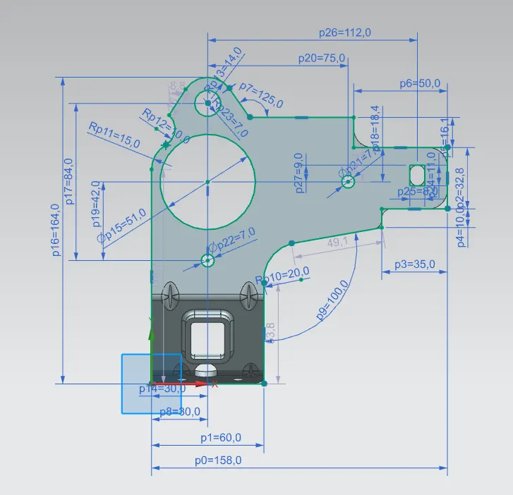
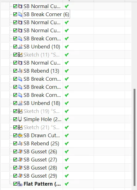
Sketch: This is used to create a basic sketh of the design on selecting the desired plane, then later it can be modeled for the requirement.
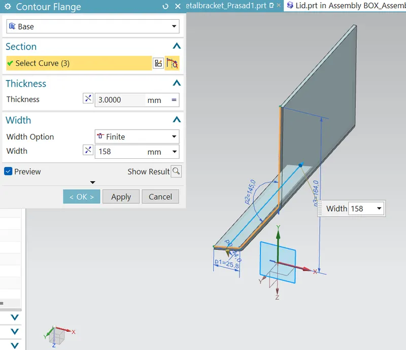
Contour Flange: It is used to create a model of sheet metal by selecting the sketch.
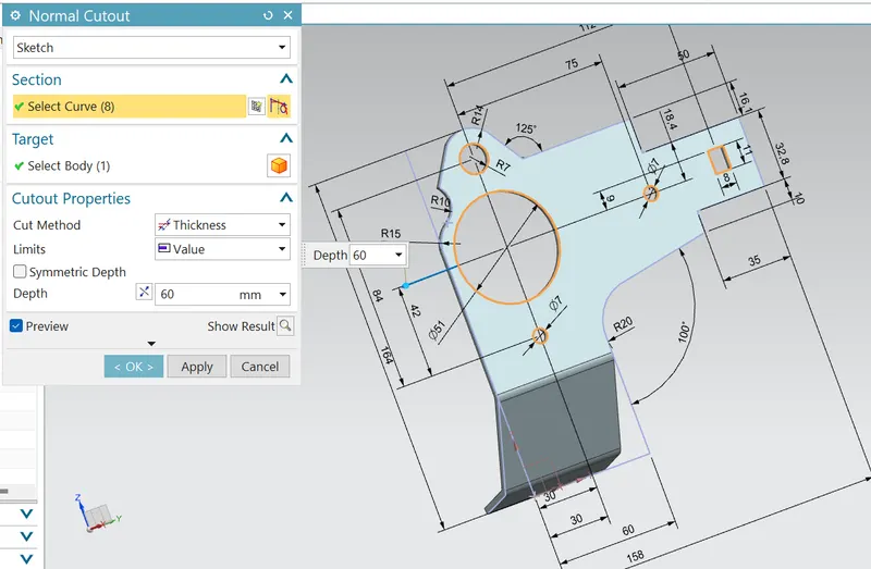
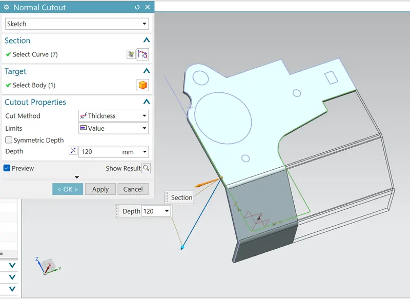
Normal cutout: This feature is used to cut the portions of the sheet metal by giving sketch curves.
Bend : This feature is used to bend the sheet metal along the skethed curve upto our requirement.
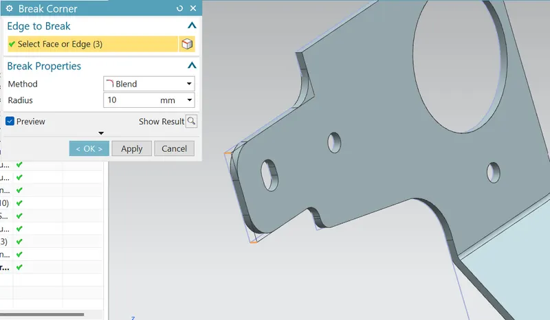
Break Cornors: Break cornor is used to make the edges round for easy handling when using.
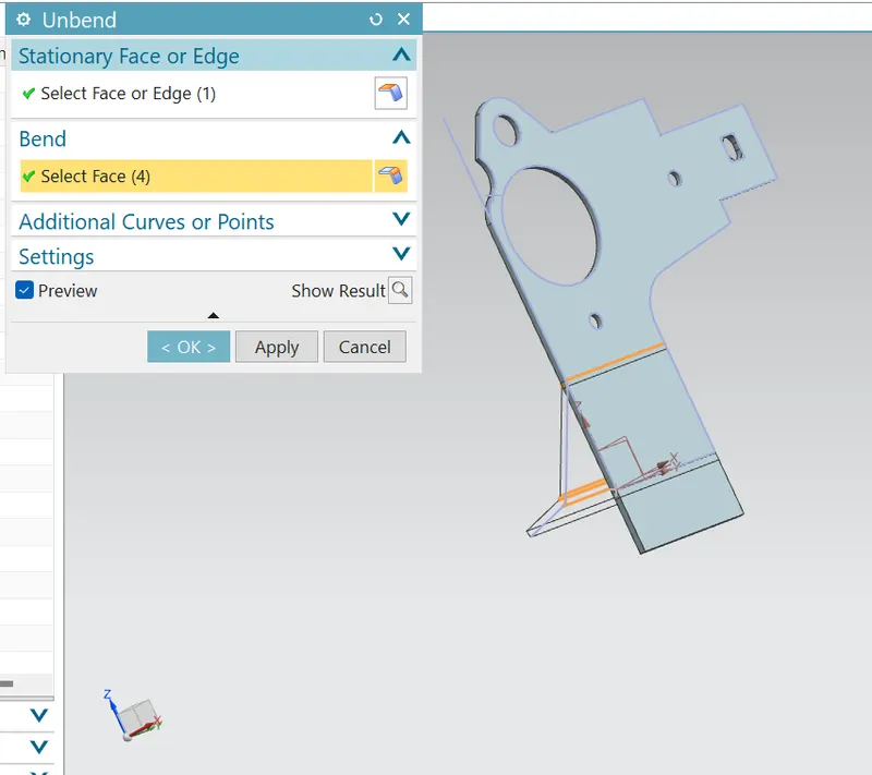
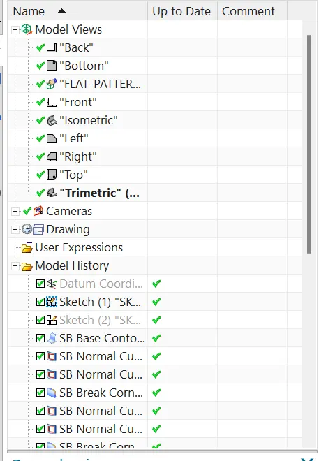
Unbend: Unbend is a feature used to analyze the model whether it has perfectly assigned the alignments, which ensures for the modeler to do further operations on it.
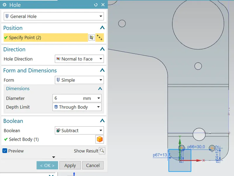
Holes: Make holes on the sheet metal by selecting the points located on the sketch.
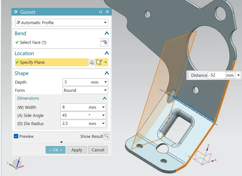
Gussets: It is used to strengthen the flange without the need for secondary process such as welding.
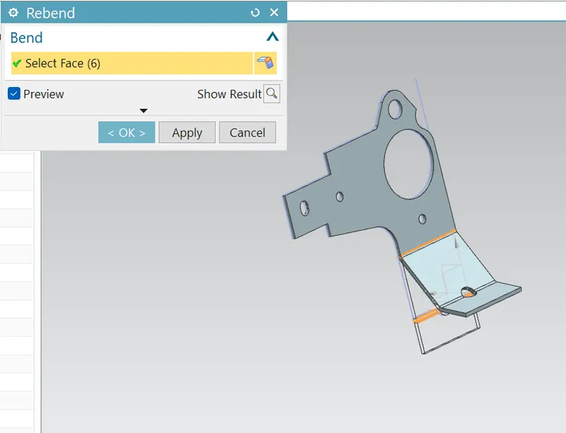
Rebend: This is used to rebend the object after all conformations.
About Gusset:
Gussets are created to improve the stiffness of the part generally gussets are created on the bend region which will connect the two faces in the specific model we are using rounded gussets.
Coonclusion:
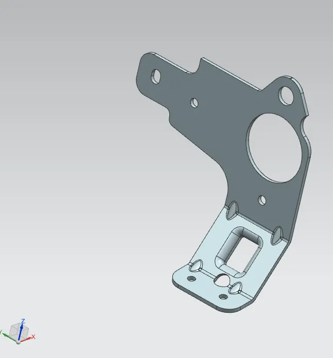
Finally a complex sheet mtal bracket part has been created. While designing the bracket i have learned how to read a 2d drawing and convert to a 3d part. Understanding of advanced features in NX CAD.
Google link:https://drive.google.com/file/d/132qisBdDoOAm9qTU792zDmQ6mPytHVQP/view?usp=sharing