Advanced Sheet Metal Design Using NX Cad
- Objective: The objective of this project was to model a sheet metal component referencing an already established geometry, as well as creating the technical drawings for communication with the production floor.
- Introduction: Sheet metal is one of the fundamental forms used in metalworking. Sheet metal parts have several advantages, including high strength, good dimensional accuracy, good surface finish, low cost, and economical mass production for large quantities. Features such as dimples, bends, and gussets can increase the part's rigidity with a minimum increase in weight and cost. The metal bracket designed here is made out of SAE 304 stainless steel for its excellent bendability.
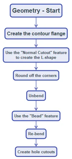
- Design methodology/approach: The basic methodology consists of creating the base tab and bends using the "Contour Flange" feature, cutting out the unnecessary portion to create the L-shape, and then rounding off the corners. The bracket is then unfolded to create the longitudinal bead to add rigidity, and finally, the part is re-bent and the holes are added to it.
- Description:
The bracket starts off by creating a sketch with the basic frontal profile. The shape mainly consists of a trapezoid with an extended base. From this sketch, the base tab is created using the "Countour Flange" feature. Afterwards, the "Normal Cutout" feature is used to cut a rectangle in order for the base to have its characteristic L-shape. The corners are then rounded off, and the part "Unbend" feature is used. Once the part is unbent, a "Bead" feature is used to add rigidity and strength to the bracket. Finally, the part is re-bent and the hole cutouts where the part will be mounted are created.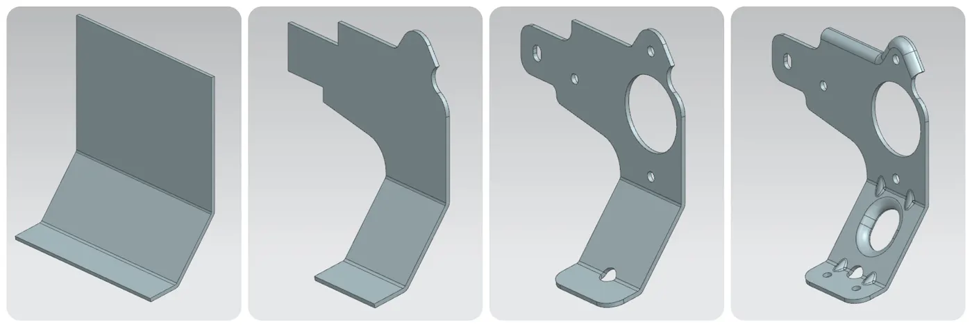
Front View: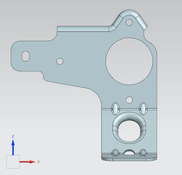
Side View: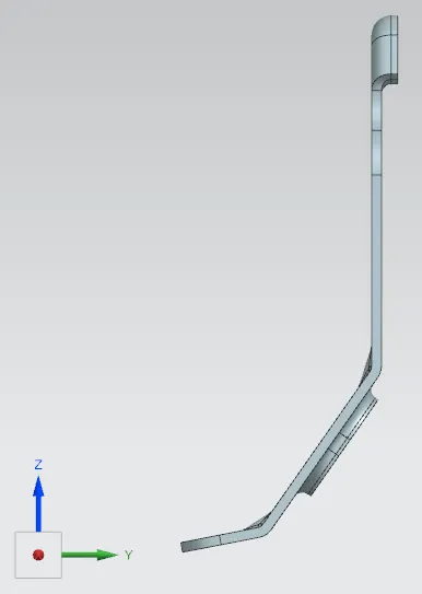
Top View: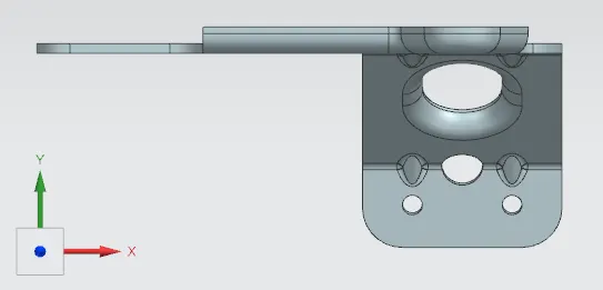
Trimetric View: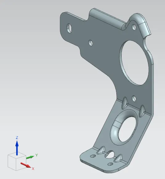
- Drawings
The drawings are the way in which the designers can communicate the dimensions, tolerance, and fabrication process to the manufacturing floor. Barring data on the machines that will be used during manufacturing, a general tolerance table is used, such as Vista Industrial Products' Industry Roecommended Sheet Metal Tolerances . The hole cutouts need to accommodate a fixed geometry; therefore, Geometric Dimensioning and Tolerancing (GD&T) is used to ensure the hole cutouts are manufactured within specifications and the part will fit on its intended position.
The basic procedure to create the drawing was the following: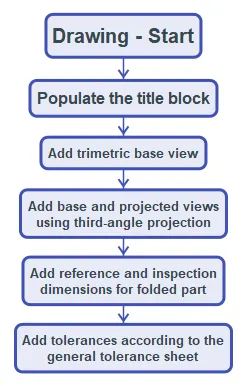
To create the drawing, the title block is first populated with the pertaining projection type, tolerance, material, finish, and drafter information, as well as data on the part's number and name, size of the sheet, number of sheets, sheet scale, and sheet revision. The trimetric base view is then added to better portray what the part looks like. The base front view is then added, and the side and top views are projected from it. Finally, the part's dimensions and tolerances are added.
The result is the following: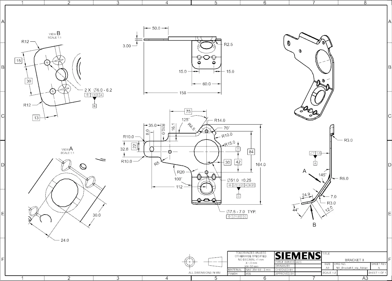
- Conclusion
In this project I have explained the process to model and draw a sheet metal casing utilizing 3 mm SAE 304 Stainless Steel using NX CAD. I have also explained my approach to determining the tolerances to be used on the part.