Creating a stainless steel sheet metal enclosure using the NX CAD Sheet Metal application
- Objective: The objective of this project was to model a sheet metal enclosure, referencing an already established inner geometry and volume, as well as creating the technical drawings for communication with the production floor.
- Introduction: Sheet metal is one of the fundamental forms used in metalworking. Sheet metal parts have several advantages, including high strength (through the use of dimples, bends, gussets, etc), good dimensional accuracy, good surface finish, low cost, and economical mass production for large quantities. Depending on the final use scenario and strength requirements for the part, different materials will be used. For this part, 304 Stainless Steel was used due to not requiring hot work or other stress relief during manufacturing. While Grade 304 SS is somewhat less corrosion-resistant than other stainless steels, it offers good formability and weldability. This particular geometry contains holes for fixing it into a surface at different angles. The shape is a prismatic trapezoid, so it presents some particular challenges when it comes to modeling.
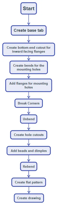
- Design methodology/approach: The basic methodology consists of creating a solid geometry and then creating a sheet metal wrapping around it. The flanges and jogs are added to the sides. Then, the part is unbent, beads and holes are added, and finally, the shape is re-bent.
- Description:
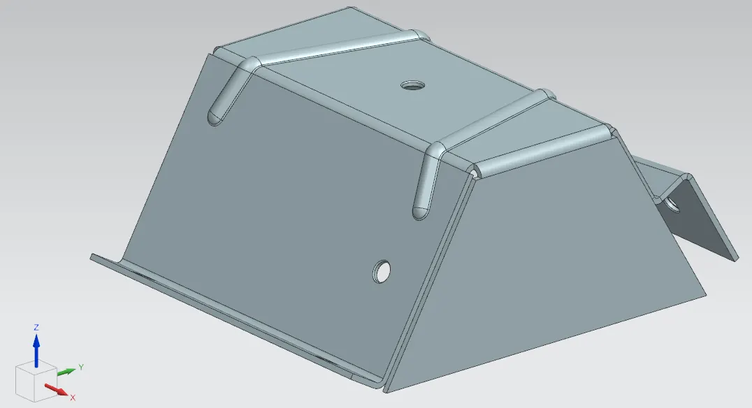
As previously mentioned, the part first starts as a solid geometry that then gets wrapped by a sheet metal, using the "Sheet Metal from Solid" feature. The flange on the front face is then added by using the "Flange" feature. On the other side, the jog is added by first making a sketch and then adding the "Jog" feature. The part is then unbent, and two beads are added to increase the part's rigidity. The holes are then added using the "Hole" feature, and the part is rebent. Finally, a "Flat Pattern" feature is used to show all the bend details that will be used later in the drawing.
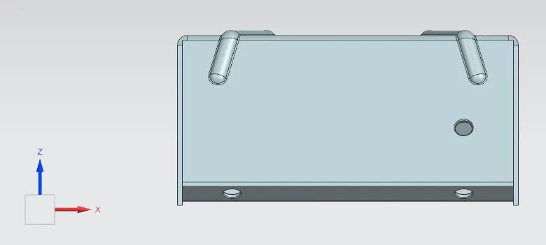
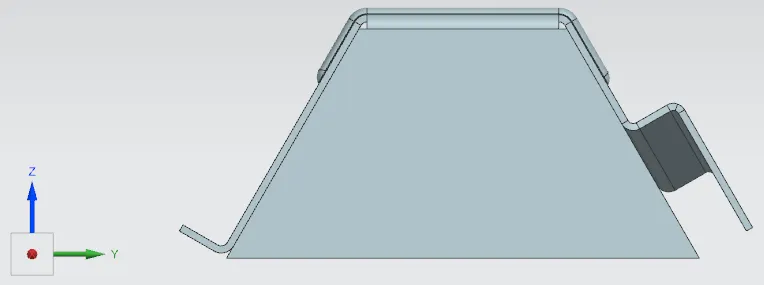
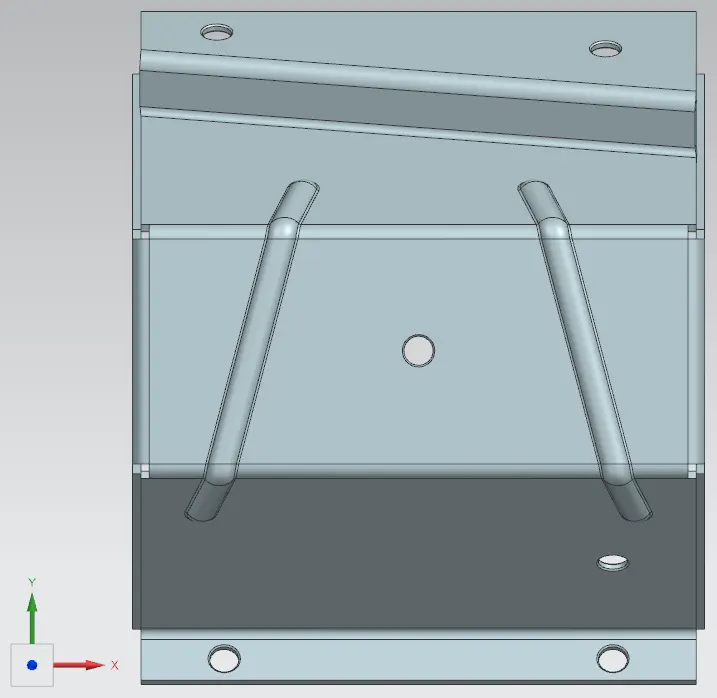
- Front, Side, Top, and Trimetric views:
- Drawings
The drawings are the way in which the designers can communicate the dimensions, tolerance, and fabrication process to the manufacturing floor. Barring data on the machines that will be used during manufacturing, a general tolerance table is used, such as Vista Industrial Products' Industry Roecommended Sheet Metal Tolerances . For most (if not all) parts, this standard procedure is followed: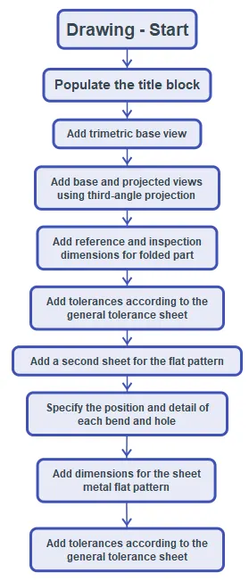
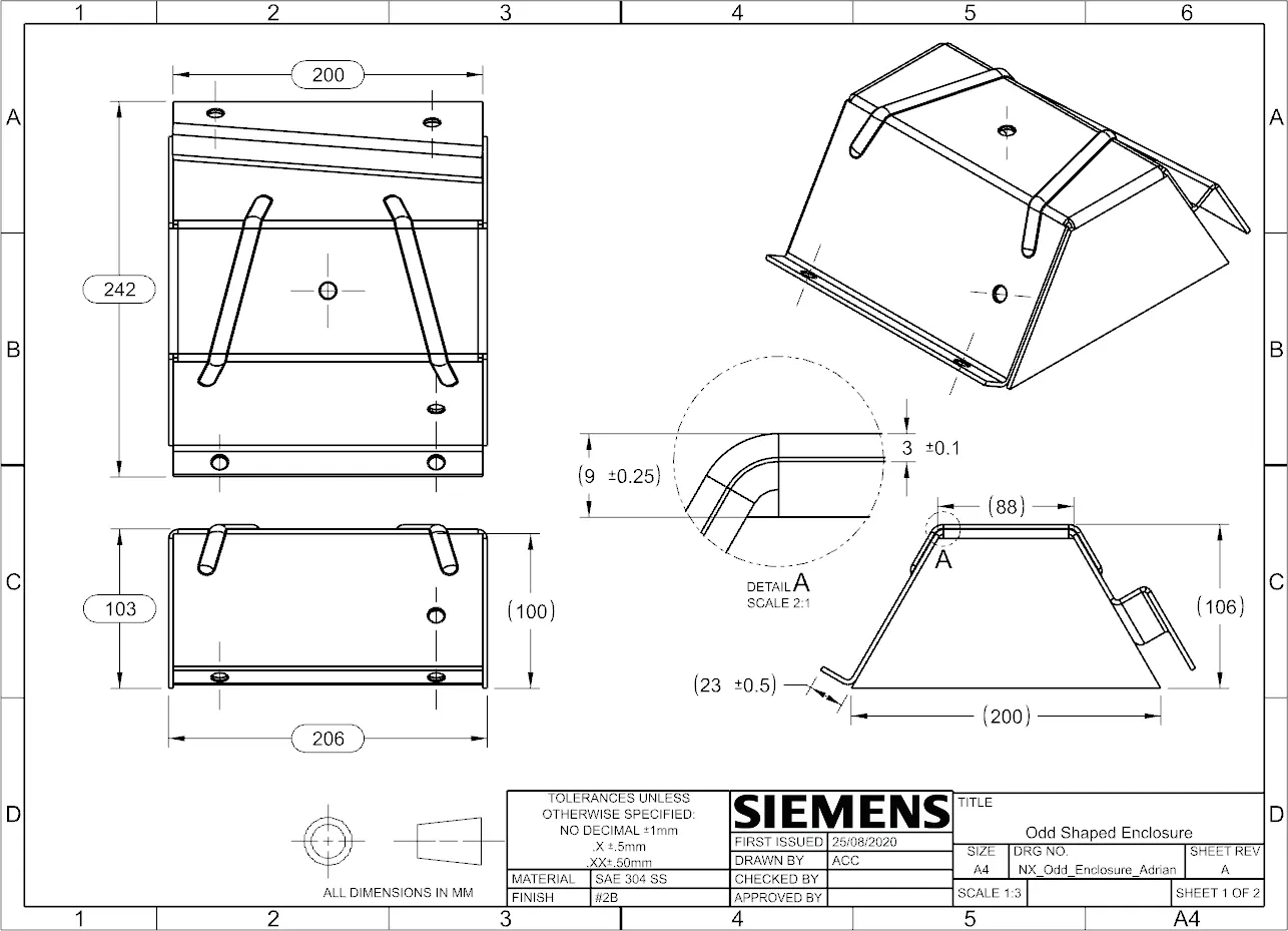
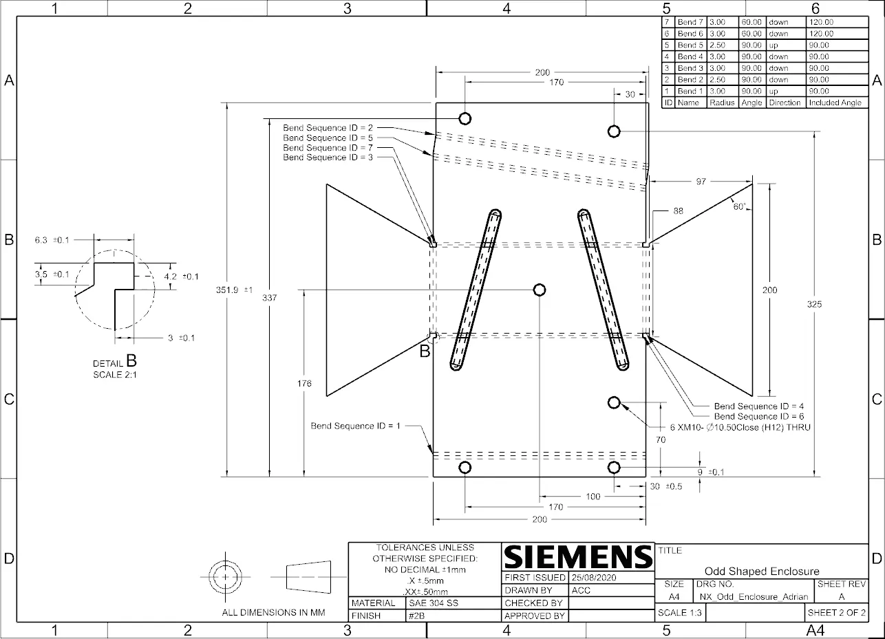
- Conclusion
In this project I have explained the modeling process to model an odd-shaped sheet metal casing and draw a sheet metal casing utilizing 1mm SAE 304 Stainless Steel using NX CAD. I have also explained my approach to determining the tolerances to be used on the part.