Creating a box assembly design using the NX CAD Sheet Metal application.
- Title of the Project: Modeling a sheet metal box using NX CAD
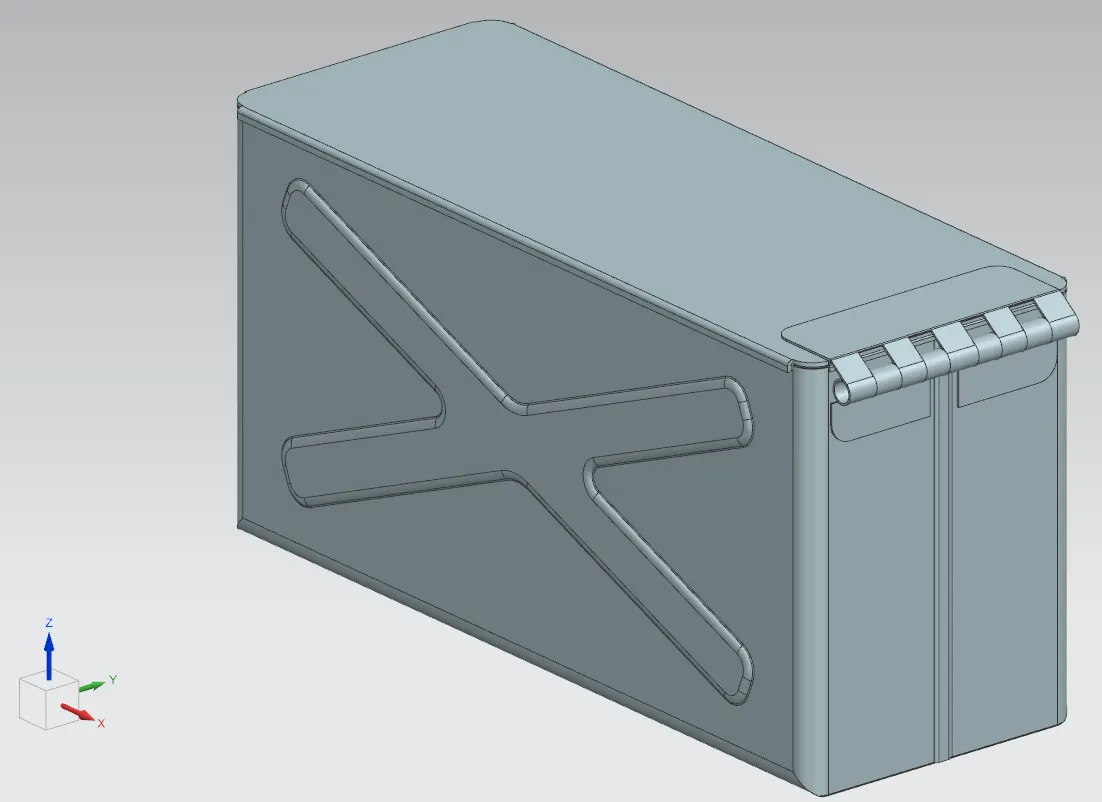
- Objective: The objective of this project is to create the model of a sheet metal box, containing a hinge and top cap, using NX CAD.
- Introduction: Sheet metal is one of the fundamental forms used in metalworking. Sheet metal parts have several advantages, including high strength (through the use of dimples, bends, gussets, etc), good dimensional accuracy, good surface finish, low cost, and economical mass production for large quantities.
- Design methodology / approach: The approach to create this assembly, is to model all the parts in-place, using NX CAD's Sheet Modeling Application.
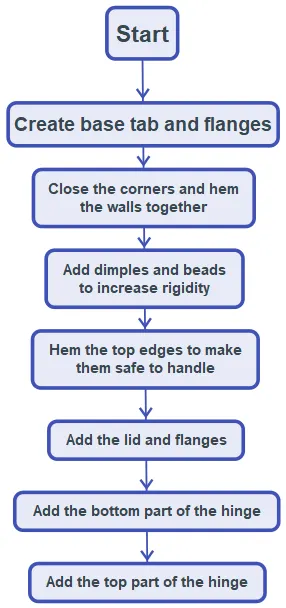
- Description (Need to explain tools/ Features used while designing)
The bulk of the box is first created by adding base tab and flanges, and then closing the corners and hemming the walls together. Bi-directional dimples are then added to the walls, to increase rigidity, as well as a single, long rectangular dimple at the bottom of the box for the same purpose. The top edges are then hemmed to allow for safe handling. The lid is then created using an offset datum plane, creating a sketch, making a tab feature, and adding flanges. Finally, the hinge is created by using the unbend, normal cutout, and circular hem features.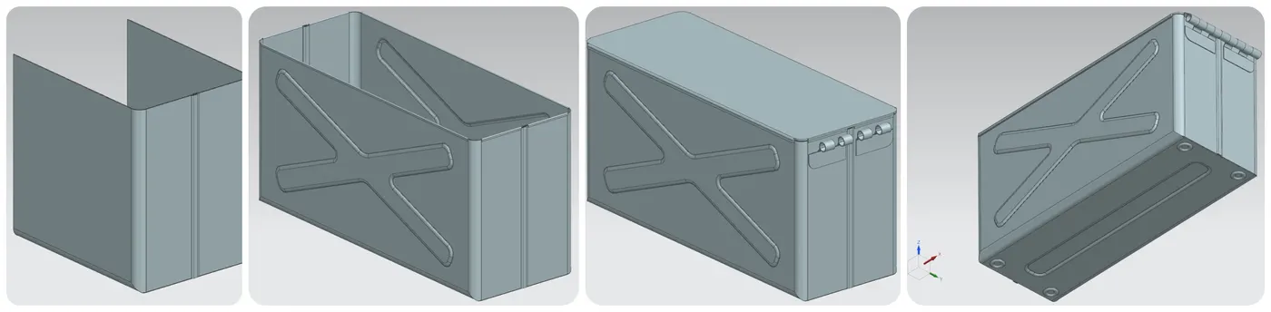
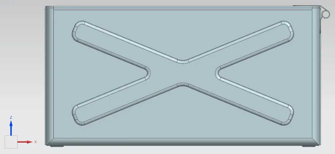
- Upload a min of four screenshots of Model in the report. (Front View, Side View, Isometric View and the Top View)
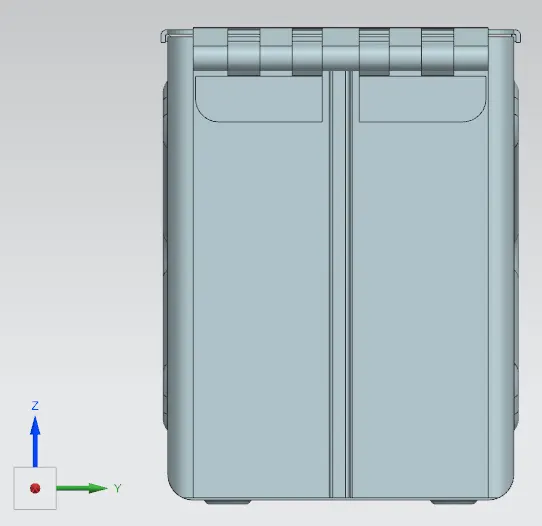
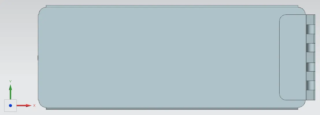
- Attach Detailed Drawing Sheet Image (If Required)
- Conclusion: In this project I have detailed my approach to creating a sheet metal box using the Sheet Metal Application inside of NX CAD, making use of the features most commonly used when modeling a sheet metal part.