Advanced Sheet Metal Design Using NX Cad Challenge_7_ Metal bracket-II
METAL BRACKET
OBJECTIVE :
- To create a sheet metal bracket using various operations performed in NX sheet metal software using 2D drawing.
- To learn and get to know the basic steps involved to perform the following model.
INTRODUCTION :
Siemens NX software is a flexible and powerful integrated solution that helps you deliver better products faster and more efficiently. NX delivers the next generation of design , simulation and manufacturing.
Sheet metal is metal formed by an industrial process into thin , flat pieces. Sheet metal is one of the fundamental forms used in metalworking , and it can be cut and bent into a variety of shapes.
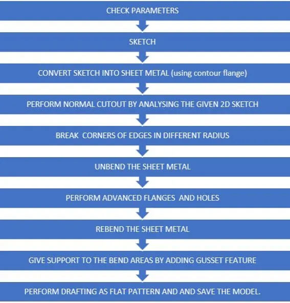
DESIGN METHODOLOGY :
TOOLS USED :
- Application – select SHEET METAL operation – This operation is used for creating a sheet metal model.
- SKETCH – This is the basic and first step for creating any model. In this , we can edit the dimensions of the sketch . To make a sketch we must first select a plane according to perspective and views.
- FLANGE – In this type of feature , we can add an extending part on the edge of the model , or we can make from sketch known as the flange. This can be changed in degree , length also.
- NORMAL CUTOUT – This feature is used to make a cutout of any shape on sheet metal. Either we can edit the sketch from the first or we can use this kind of operation.
- BREAK CORNER – This feature is used because while making flange the edge still has a sharp corner . So , to tackle we use the break corner feature.
- UNBEND – This command is used to unbend all the bend areas of the sheet metal . Resulting in an even and flat pattern surface of the sheet metal.
- HOLE – This is a cutout feature where the sketch can only be made in circles only.
- REBEND – This operation is the opposite of bending operation . In this , we can rebend all flanges and bent areas to the original shape of the sheet metal.
- GUSSET – It is a feature added to give stiffness to the bent sheet metal part hence increasing the strength of the part.
VIEWS :
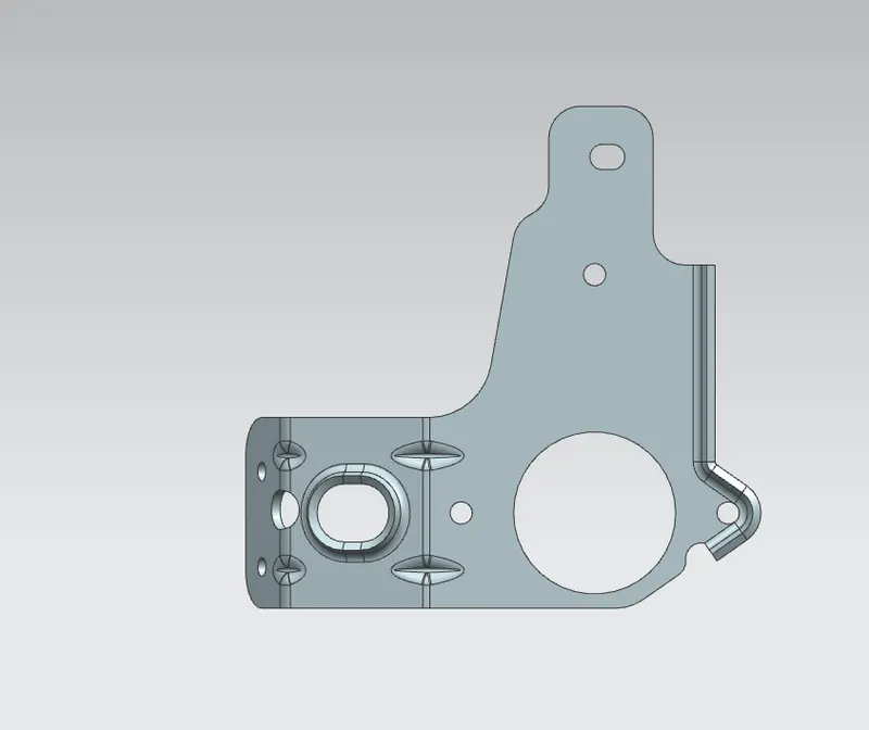
ISOMETRIC VIEW
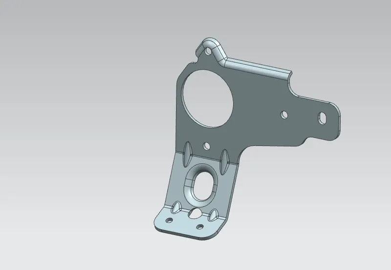
FRONT VIEW
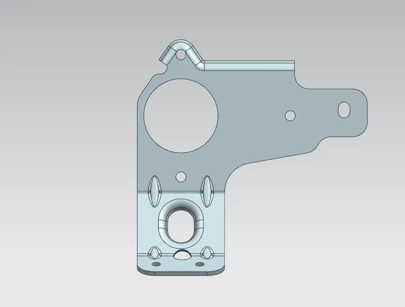
TOP VIEW
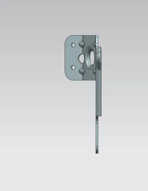
SIDE VIEW
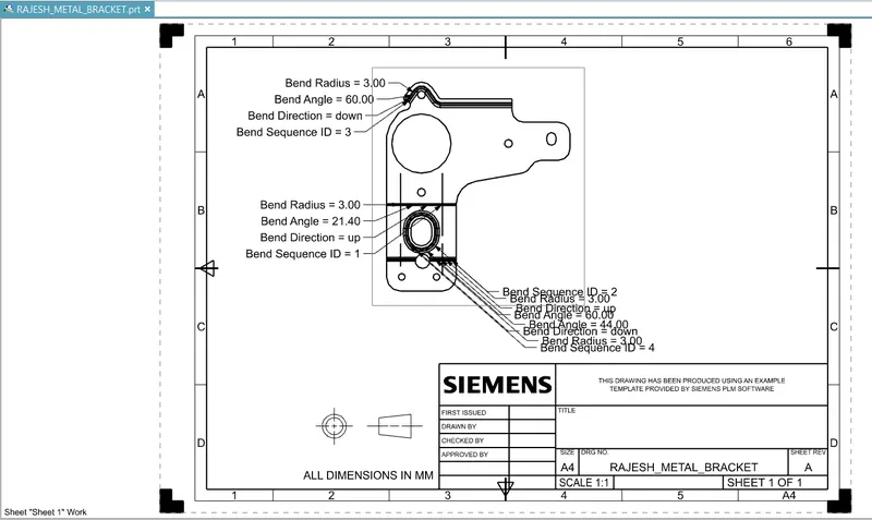
DRAWING SHEET
CONCLUSION :
Hence the designing of the sheet metal bracket is completed using the various tools and commands that were available in NX cad software and drafting as well.