Advanced Sheet Metal Design Using NX Cad Challenge_7_ Metal bracket-II
Title of the Project:
Bracket- II
OBJECTIVE:
To design a Bracket using sheet metal.
INTRODUCTION:
In this project we design the Bracket using sheet metal by using the tools such as contour flange, normal cut-out, Break corner, unbend, bead, holes and Rebend.
DESIGN METHEDOLOGY:
STEP1: Create Sketch XY plane
STEP 2: Create Sketch XY plane
STEP 3: Create contour flange
Step 3: use normal cut out
Step 4: break all the corners
Step 5: unbend Sheetmetal
Step 6: use advance flange
Step 7: unbend the Sheetmetal
Step 8: create normal cut out
Step 9: use advance flange
Step 10: re bend
Step 11: add gusset
DESCRIPTION:
The features used to create dimple are
1.sketch: It is used to create the 2D sketches.
2.Contour Flange: It is used to make base with the sketch without tab.
3.Normal cut-out: this tool is used to cut the sheet metal with the directions.
5.Unbend: It is used to unbend the component.
6. Rebend: It is used to Rebend the component
7.Bead: It is used to make beads on surfaces.
8.Hole: It is used to make holes for the sheet metal.
9.Gusset: It is used to give more strength to the sheet metal.
MODEL IMAGES:
Front View:
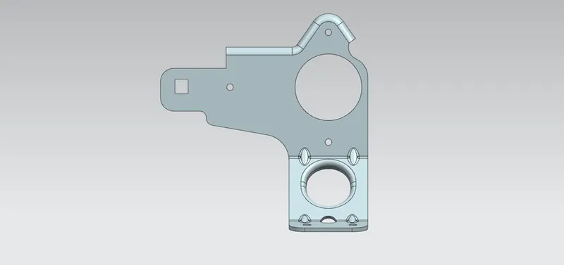
Top View:
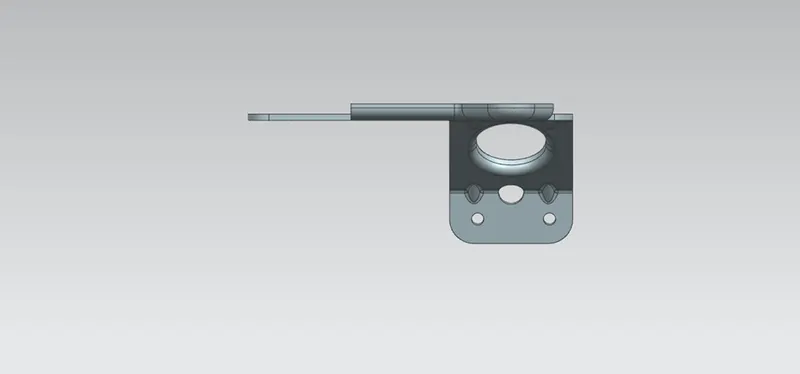
Side View:
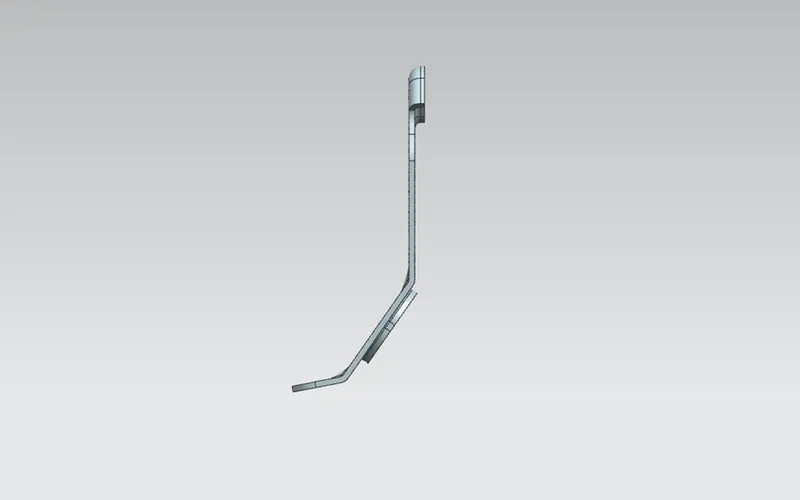
Isometric View:
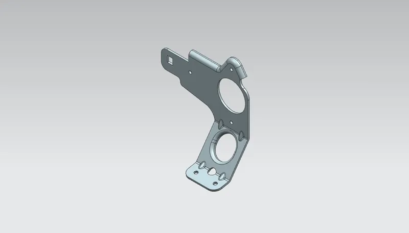
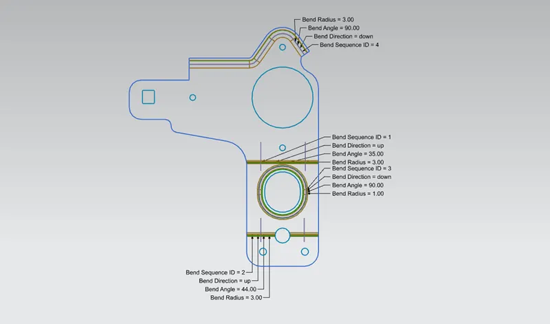
Flat Pattern View:
Conclusion:
Bracket design was done successfully in sheet metal by using Siemens NX.