Advanced Sheet Metal Design Using NX Cad Challenge_7_ Metal bracket-II
METAL BRACKET
USING
NX CAD
SHUBHAM H POTBHARE
OBJECTIVE
In this project we are going to learn the entire modelling of Metal Bracket using NX Cad.
INTRODUCTION
NX Cad 12.0.1 version is used for modelling. NX sheet metal provides a set of tools within the NX design environment that allows for simple and fast design of sheet metal parts. In this project we will learn to use them and create a sheet metal bracket using NX Sheet Metal and its commands.
DESIGN METHODOLOGY
DESCRIPTION
Step 1 : Create the Sketch in YZ plane according to the given dimensions.
Step 2 :
Create the Sketch of Side View of model in XZ plane and apply Contour Flange Command.
Step 3 :
Then Normal Cut out Command is used to remove extra material from the first Sketch in YZ plane.
Step 4 :
Break Corner Command is used to give Fillet at the required areas.
Step 5 :
Then the Unbend Command is used to Unbend te model and Flatten it.
Step 6 :
Select the Sketch option to create circle and Normal Cut out is used to remove the circular part.
Step 7 :
Finally bend the model again using Rebend Command.
Step 8 :
Use the Advanced Flange Contour as shown in the sketch image.
Step 9:
Lastly use the Gusset Command according to the sketch image.
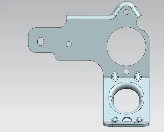
FRONT VIEW
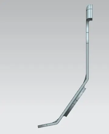
SIDE VIEW
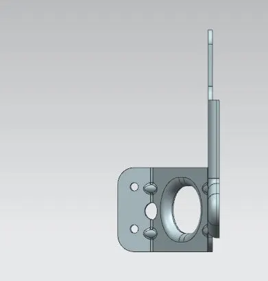
TOP VIEW
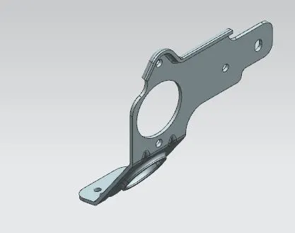
ISOMETRIC VIEW