Advanced Sheet Metal Design Using NX Cad Challenge_7_ Metal bracket-II
Objective : To design 3D CAD model of Metal Bracket using NX 12
Introduction :
NX is the the most powerful, flexible, and innovative product development solution in the industry. NX for Design has the features, performance, and capabilities to help you get product to market faster than ever before
NX for Design enables you to deliver products “right to market, first time" using more virtual product models and fewer, more costly, physical prototypes. This leads to market gains, lower development costs, and improved product quality.
In this project we will learn the recommended workflow procedure to design a 'Metal Bracket' using Siemens NX Sheet Metal Application.
Design Methodology
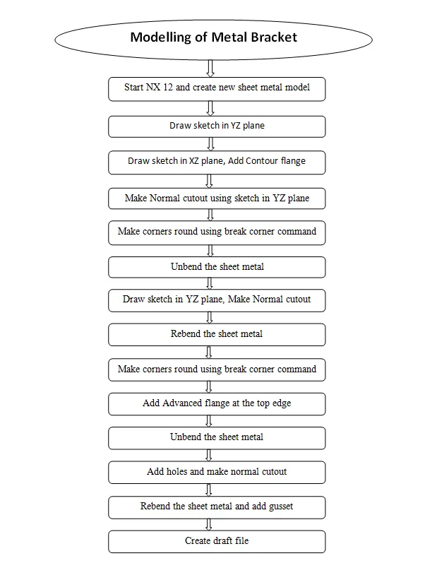
Description :
The design procedure of the Bracket is explained in detail as follows
1. Sketch & Contour flange
Create sketch in YZ plane, create another sketch XZ plane and add contour flange
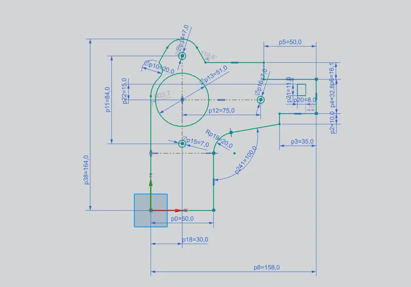
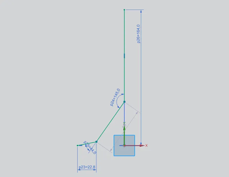
Contour flange
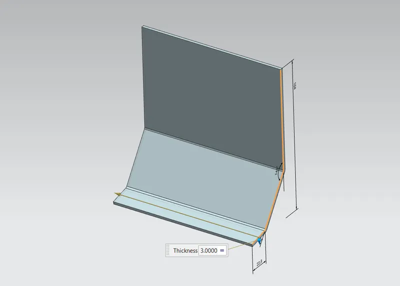
2. Normal Cutout & unbend
Draw sketch and make normal cutout using given dimensions and unbend the sheet metal to add another cutout
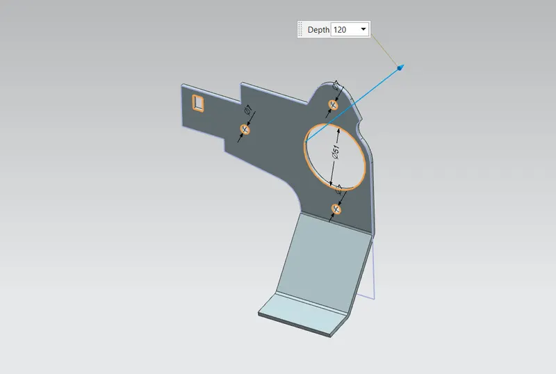
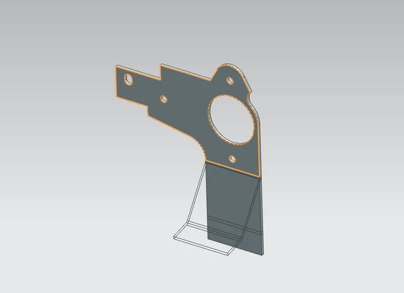
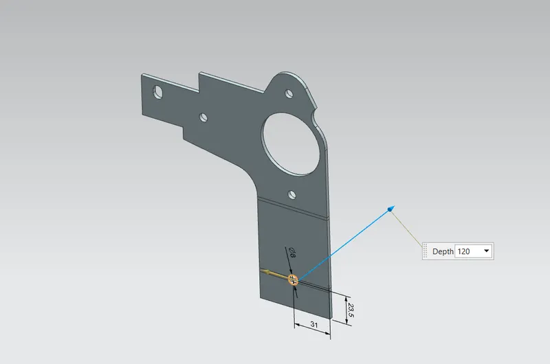
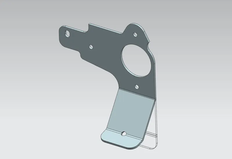
2. Break Corner & rebend
Make the corners round using break corner command using given dimensions and rebend the metal sheet
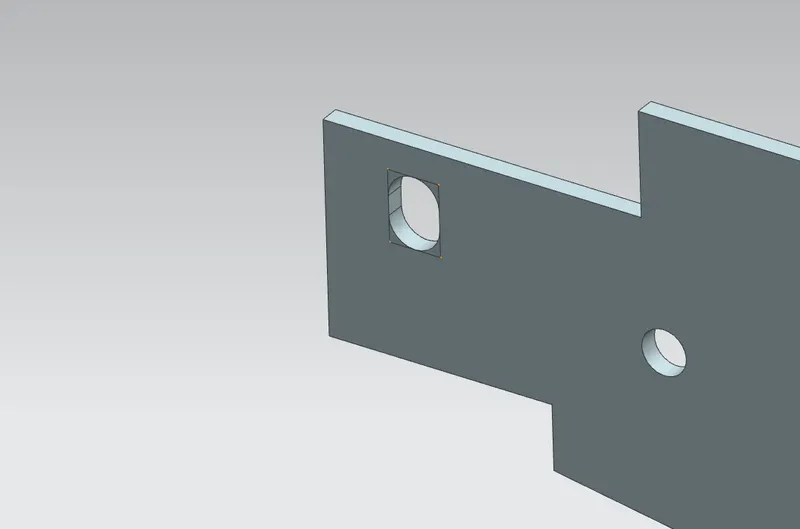
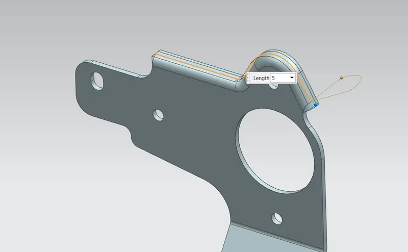
3. Advanced flange
Add flange at the top edge using advanced flange command as per given dimensions
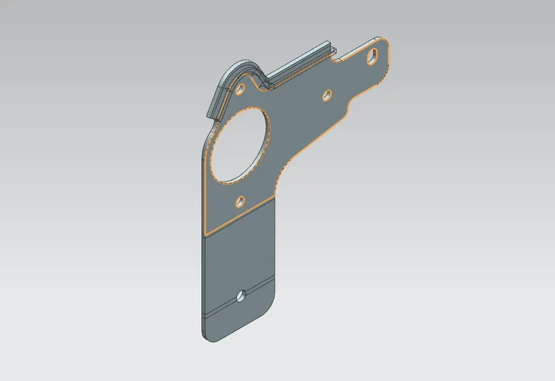
4. Unbend
Unbend the sheet metal to add more feature like holes, flanges, beads, etc
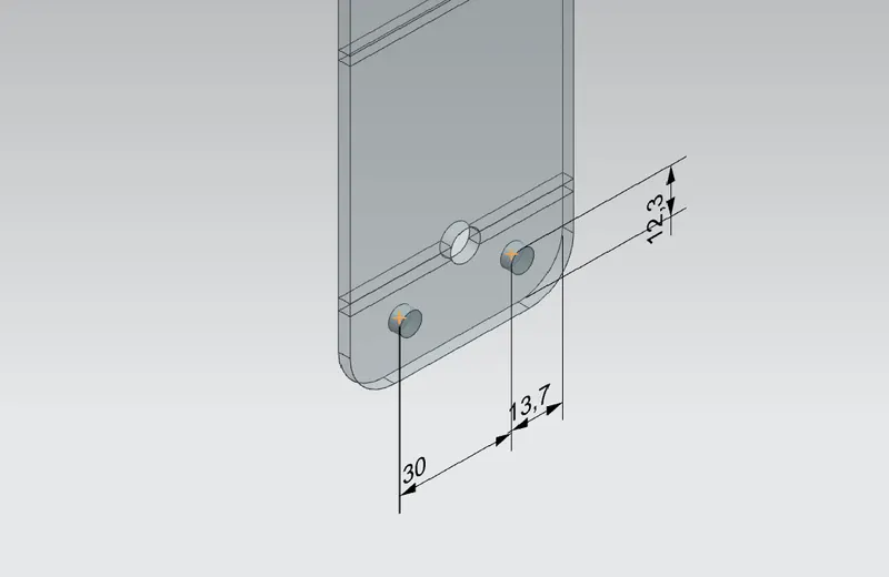
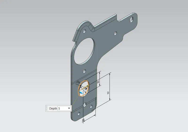
5. Holes and Normal Cutout
Add simple holes using hole command as per given dimenions, Draw a new sketch on the sheet surface and use normal cutout feature
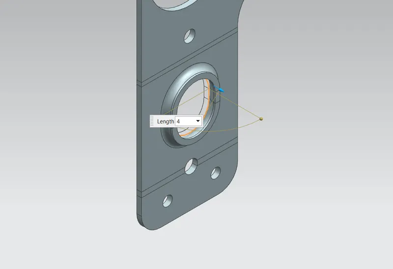
6. Advanced flange
Add advanced flange at the edge of the newly created cutout using given dimensions
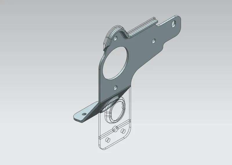
7. Rebend
Rebend the sheet metal using rebend command
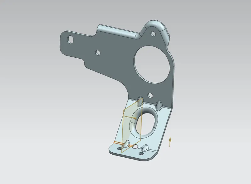
8. Add Gusset
Add gusset using given dimensions
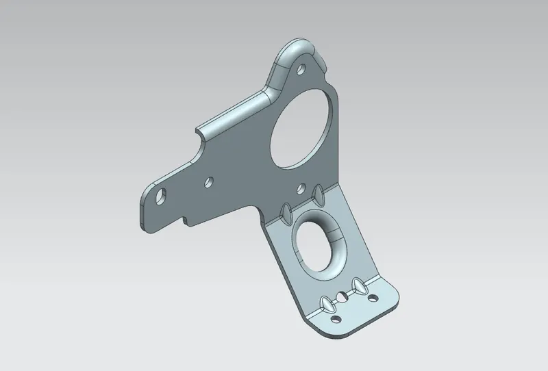
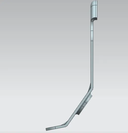
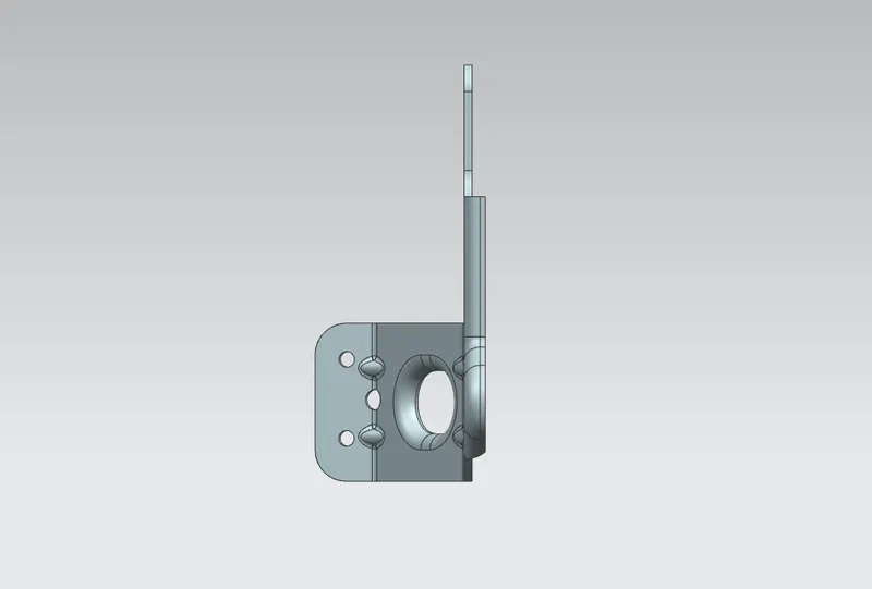
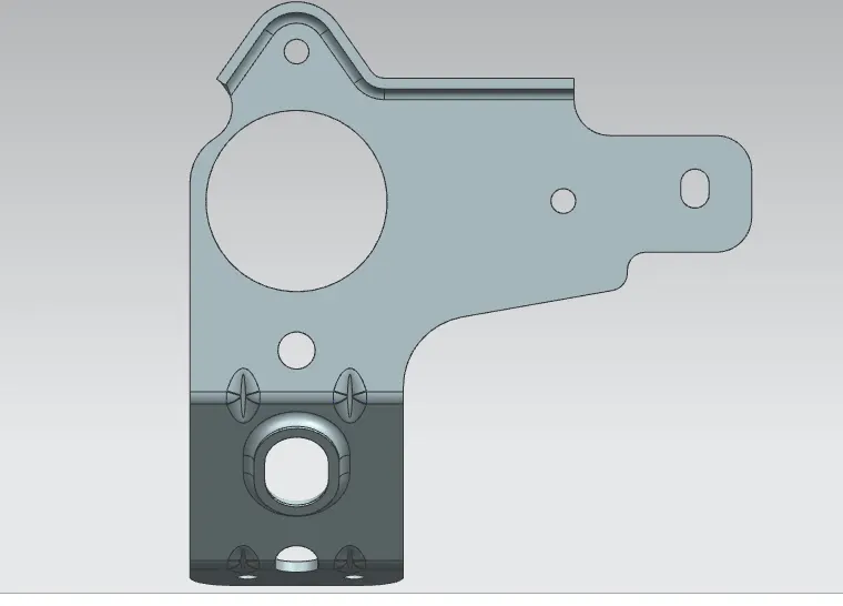
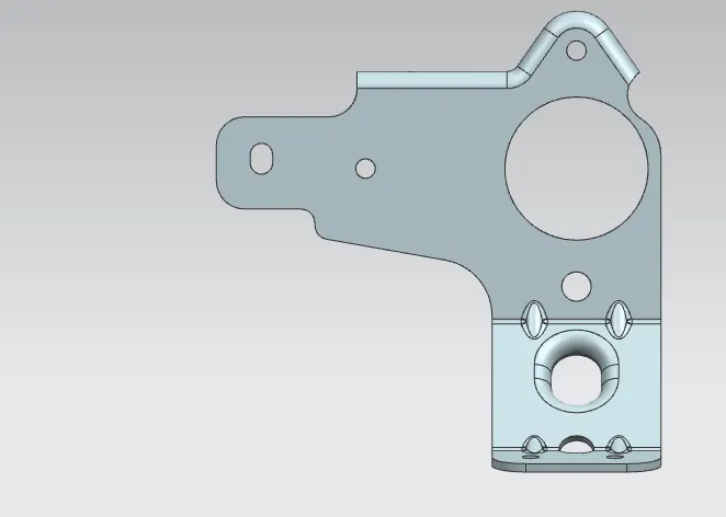
MODEL STANDARD VIEWS
ISOMETRIC VIEW
FRONT VIEW
TOP VIEW
RIGHT SIDE VIEW
LEFT SIDE VIEW
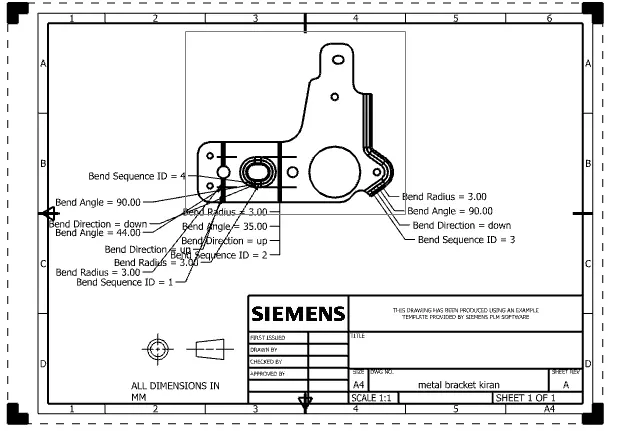
Drawing Sheet
Conclusion :
Modelling of Metal Bracket is done successfully using NX 11