Advanced Sheet Metal Design Using NX Cad Challenge_5_Odd Shaped Enclosure
Objectives:
To learn the workflow procedure to design sheet metal odd shapes or angles by using Siemens NX sheet metal
Introduction:
Sheet metal is simply metal formed into thin and flat pieces. It is one of the fundamental forms used in metalworking and can be cut and bent into a variety of different shapes. Countless everyday objects are constructed of material. Thicknesses can vary significantly, although extremely thin thicknesses are considered foil or leaf, and pieces thicker than 6 mm (0.25 in) are considered plate.
Design methodology:
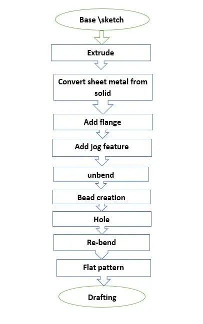
in this design sheet metal odd shapes or angle design process we used different tools. The design methodology used for this project step by step procedure is shown in below flow chart
Description:
To Design sheet metal odd shape procedure steps are clearly described in below following steps
Sketch:
Sketch is the fundamental base element of design for any sheet metal component. Most of the features require a sketch. For to design sheet metal, odd shapes or angle design Create a sketch in the “ZX” plane and draw a sketch at the origin with given dimensions
Extrude:
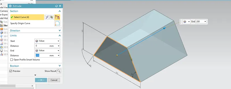
Create a solid feature by extruding a section along a vector. for this odd shape, the sheet metal design gives a distance of 200mm as shown in the below figure. (Home tab: design features Gallary-more-extrude)
Wrap the solid model with sheet metal:
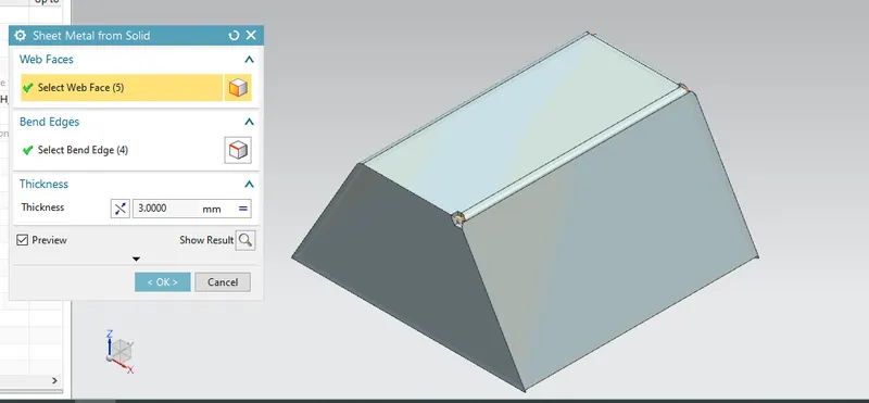
Builds a sheet metal model that takes its shape from a collection of the planner's faces. For this project from the top side are selected as bend edges total 4 bend edges and 5 web faces. (Home tab: basic Gallary-sheet metal form solid
Flange:
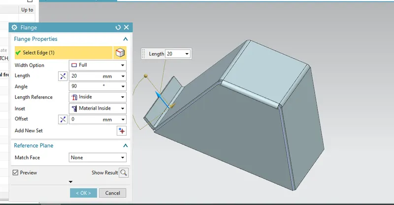
adding a flat flange at an angle to a planar surface and adds a bend between the two. For odd shape design adding flange on the left view of the model with 20 mm length & angle 90. (Home tab: bend gallery– bend
Jog:
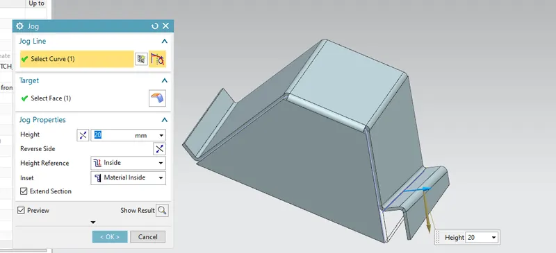
Modify the model by lifting material on one side of a sketch line, adding a flange between two sides. for this project draw an inclined line on the right view side of the model and add a jog with 20mm height. (Home tab: bend gallery– more -jog)
Unbend:
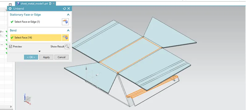
flatten a bend and the material adjacent to the bend. in the unbending dialog box select stationary face (Home tab: form -unbend)
Bead:
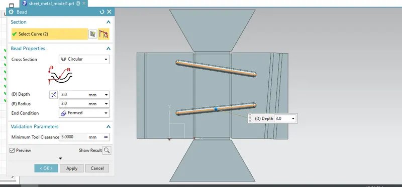
create a solid using a path and a cross-section shape. For sheet metal, odd shape design beads are applied in parallel inclination as shown in the below image (Home tab: punch gallery-bead)
Hole:
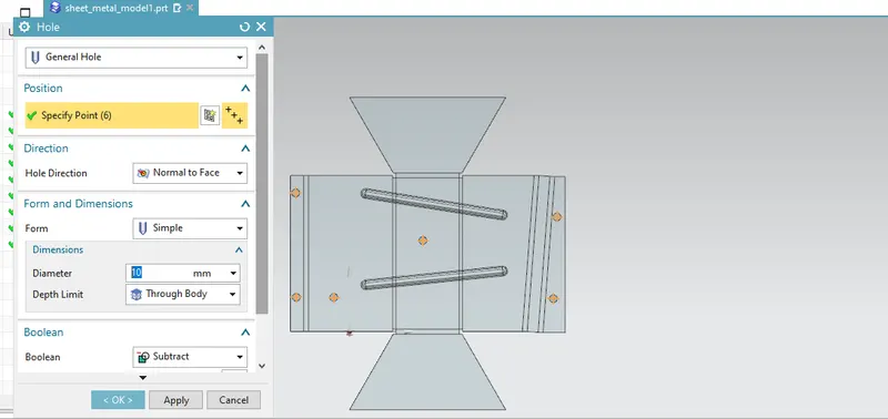
adding a hole to one or more solid bodies in part or assembly with options for countered bored, countersunk, and threaded. for odd shape sheet metal design sketch four points figuring the centers of the four wanted holes as shown in figure (Home tab: features gallery-more- hole)
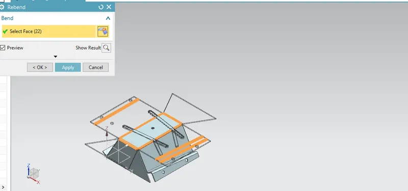
Re-bend:
Restore an unbend feature to its previous bend state along with any features added after the unbend feature
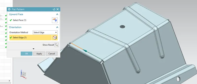
Flat pattern:
creates a flat pattern feature from the formed sheet metal part. (Home tab-flat pattern gallery)
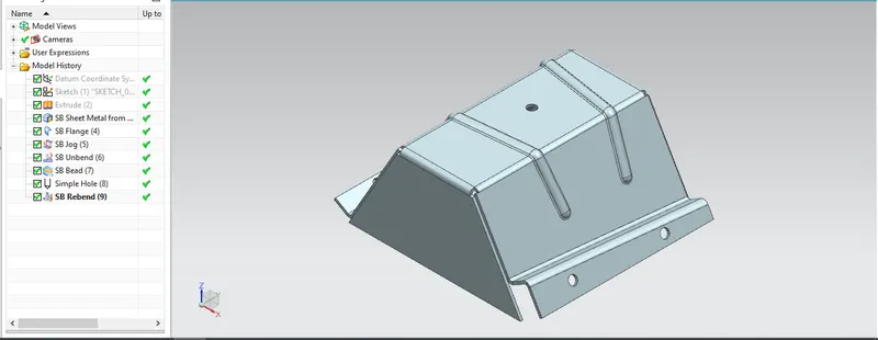
Different views of the sheet metal odd shape:
Isometric view of the odd shape:
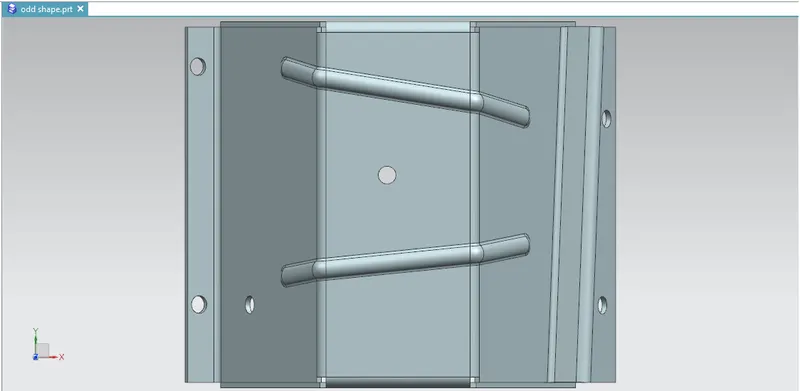
Top view of the odd shape :
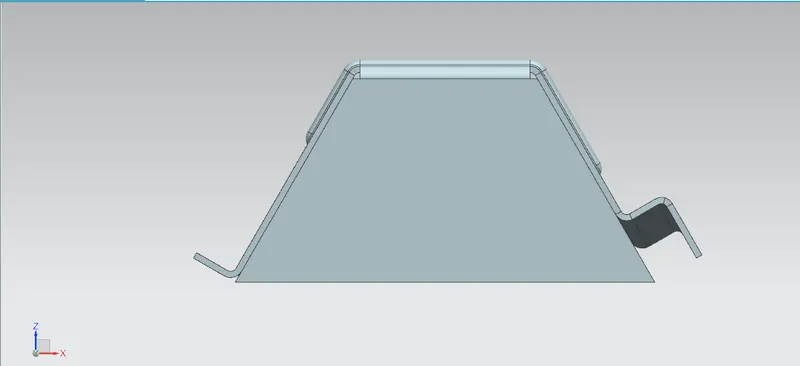
Right view of the odd shape:
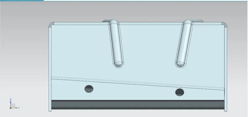
Front view of the odd shape:
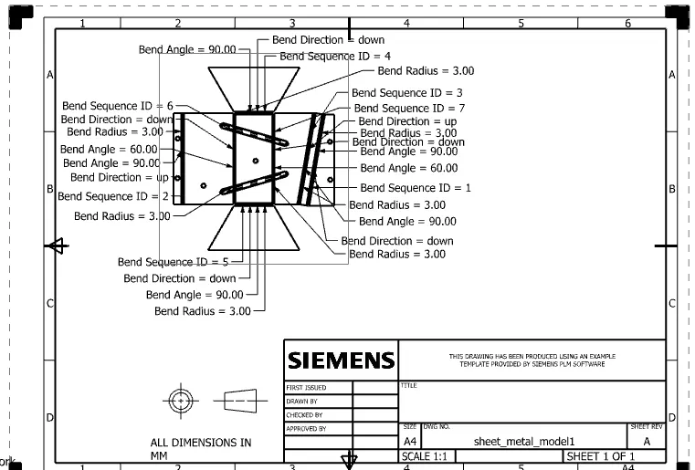
Drawing sheet
Conclusion :
Hence the odd shape enclosure is being created in the sheetmetal