Advanced Sheet Metal Design Using NX Cad Challenge_7_ Metal bracket-II
Title of the Project : Advanced Sheet Metal Design Using NX Cad Challenge_7_ Metal bracket-II.
Objective : To design a Sheet Metal Design Using NX Cad sheet metal application.
Introduction :
Unigraphics NX (also known as Siemens nx) is an advanced High-end CAD/CAM/CAE software package originally developed by UGS Corporation, But since 2007 it is owned by Siemens PLM Software. It is used, among other tasks, for Design ,Engineering analysis ,Manufacturing finished design by using included machining modules.
NX Sheet Metal provides a set of tools within the NX design environment that allows for simple and fast design of sheet metal parts, dependent on their material and manufacturing process, the most common of which is straight brake sheet metal forming.
Design methodology :
Description :
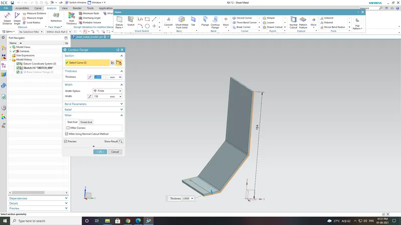
Contour flange :Ads flange on an edge and create a bend between two walls. The flange can only be made on a straight edge.To activate command.Click on command on (When sheet metal application activated.) “ Home => Bend Group => Flange”Activate command from “Menu => Insert => Bend => Contour Flange”
Break corners: It breaks the sharp edges of the corner and make smooth like fillets or chamfer. It prevent the fracture breaking from the sharp corners.
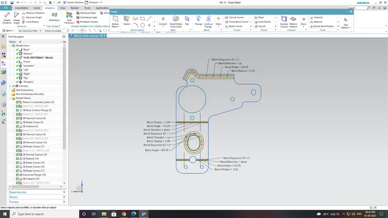
Unbend : It allows all the bend to unbend sheet.It is necessary to choose the bend, it can also to box select all the bend at once.
Hole : Hole feature is just like the same as the put a hole in the sheet eith respective measurements of sketch.
Flat pattern: Create a flat pattern from the formed sheet.
Procedure:
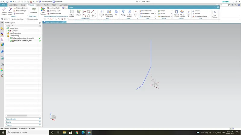
Create a skecth and contour flange accordingto the sketch.
With the thickness of 3 mmand width 150.
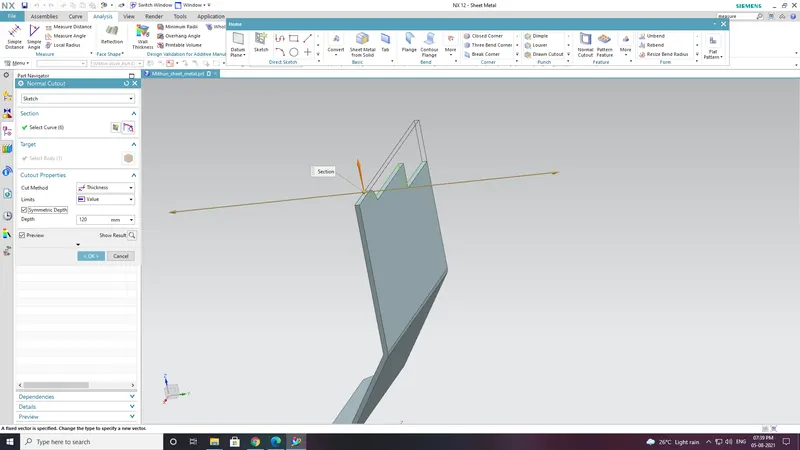
Give the normal cut according to the sketch.
And give break corner where ever it needs.
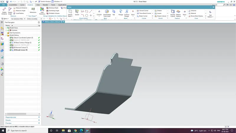
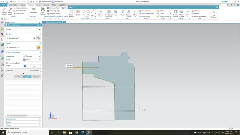
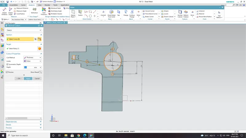
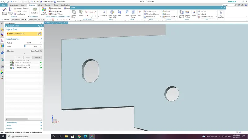
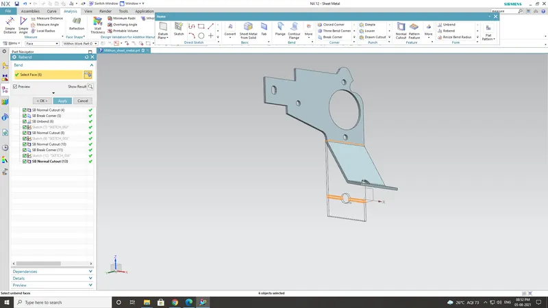
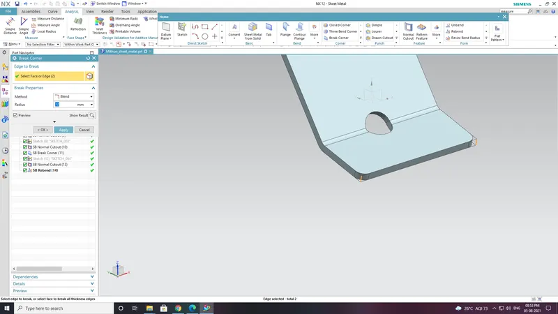
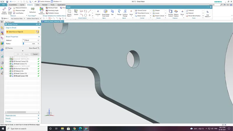
Unbed it and create a advanced flange with the length of 5mm and angle 90 deg.
Crearte a 2 hole according to the measurements.
Create a normal cutout with the specific sketch.
And create a advanced flange in theat cut out with length of 4mm .
Rebend it
Add a guesst for that choose the plane and select the face and give the distance of -15 mm.
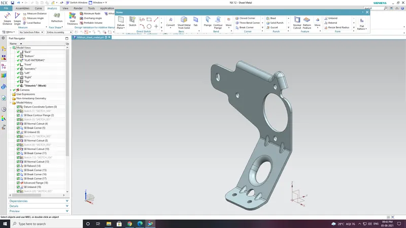
Final resullt is Metal Bracket.
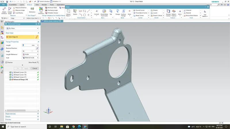
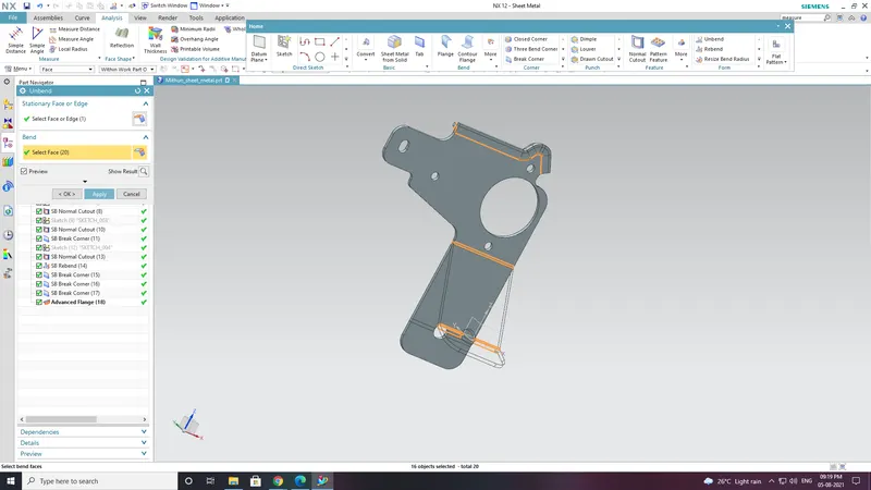
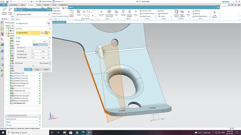
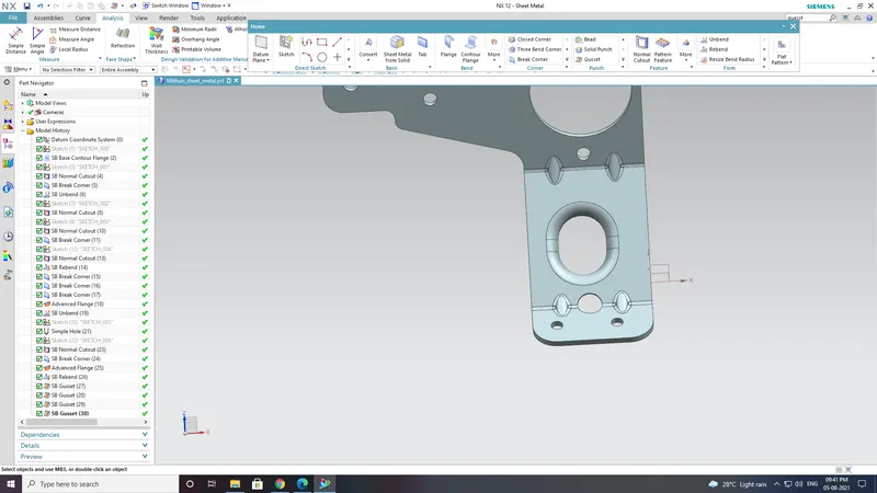
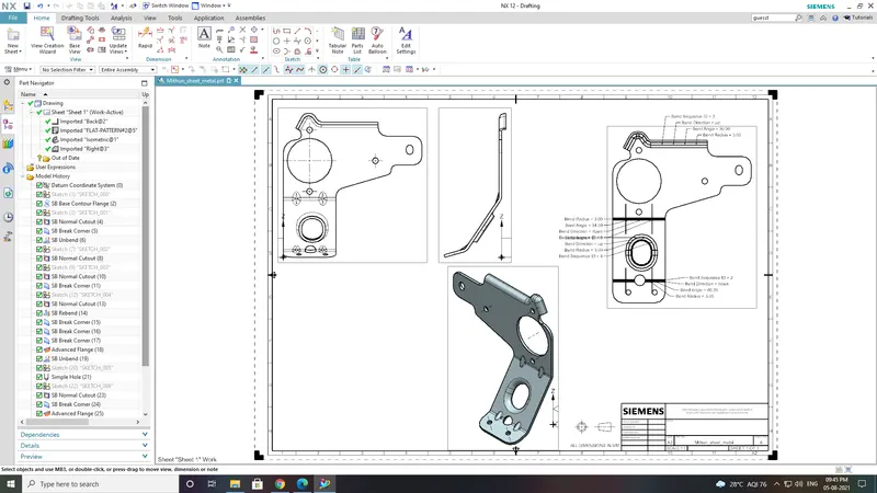
Attach 4 images with proper standard views of modeling :
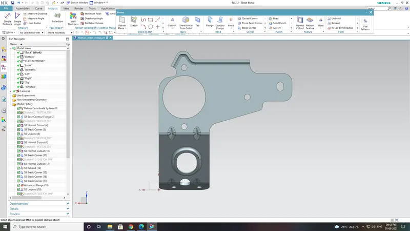
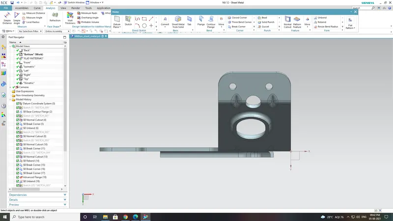
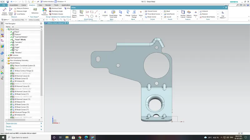
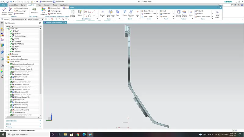
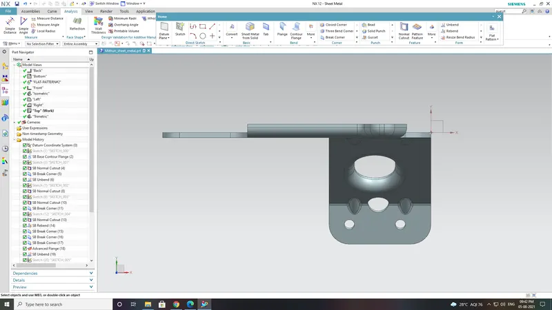
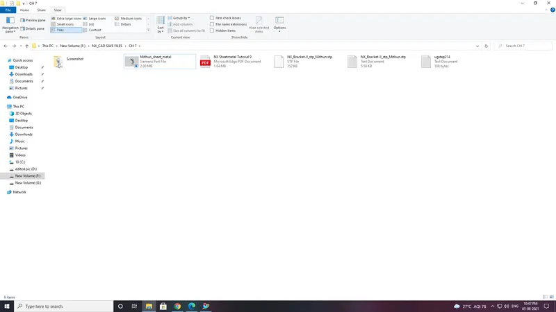
Save the models with your name in prefix or suffix to the part name.
.stp format.