DESIGNING SHEET METAL BRACKET II USING SIEMENS NX.
TITLE: DESIGNING SHEET METAL BRACKET II USING SIEMENS NX.
OBJECTIVE:
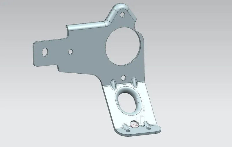
Learn to design a sheet metal bracket from given 2-d drawing in an industrial manner.
INTRODUCTION:
Sheet metal parts are widely used in machinery, enclosure, brackets, and automobile due to its various advantages. The parts are normally manufactured with break press. Sheet metal is nothing but the thin sheets made from metal of size ranging from 0.5 to 6mm. In this project I used NX CAD tool for designing the sheet metal bracket. NX CAD is used as design tool in more than 85% of the sheet metal industries.
In this project, a bracket is designed in Siemens NX CAD software following the industrial approach. The use of parametric modelling environment is the main use made in this project. The project focuses on the stiffening process of a bracket with the application of advanced flange and gussets. All the sheet metal design consideration are carefully considered while doing this project.
DESIGN METHODOLOGY:
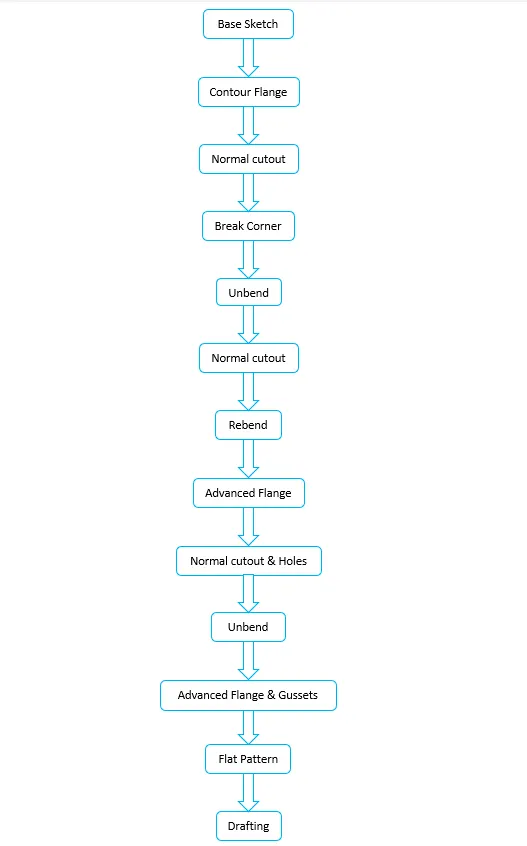
Simple and easy design methodology is followed during this project. Only thing is that we have to just keep an eye on the base sketch dimensions and relations as well as order of unbending and rebending the of bracket. Contour flange, Normal cutout, break corner are the some of main features used while this project. The design methodology used for this project is summarized in below flowchart.
DESCRIPTION:
Sketch:
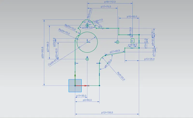
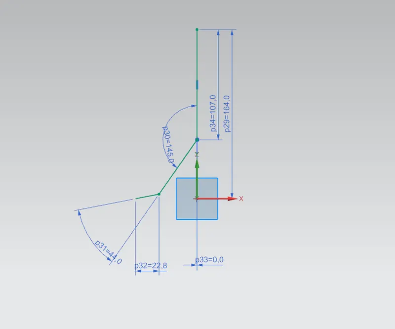
For creating any sheet metal surface, we have to first make a sketch. So, I started with creating base sketch on YZ plane which will be later used for normal cutout repeatedly. After that I create another sketch on ZX for creating the contour. Other than contour, various sketches are also made on different planes or faces for creating other different part during designing.
sketch on YZ plane:
Sketch on ZX plane:
Contour Flange:
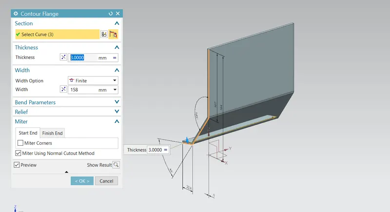
It is used to extrude sketch along the vector or adds material by sweeping a sketch along an edge or chain of edges. For this project of bracket designing, Contour flange was created by using the sketch on ZX plane as a curve. Contour flange had parameters as thickness = 3mm and width = 158mm.
Normal cutout:
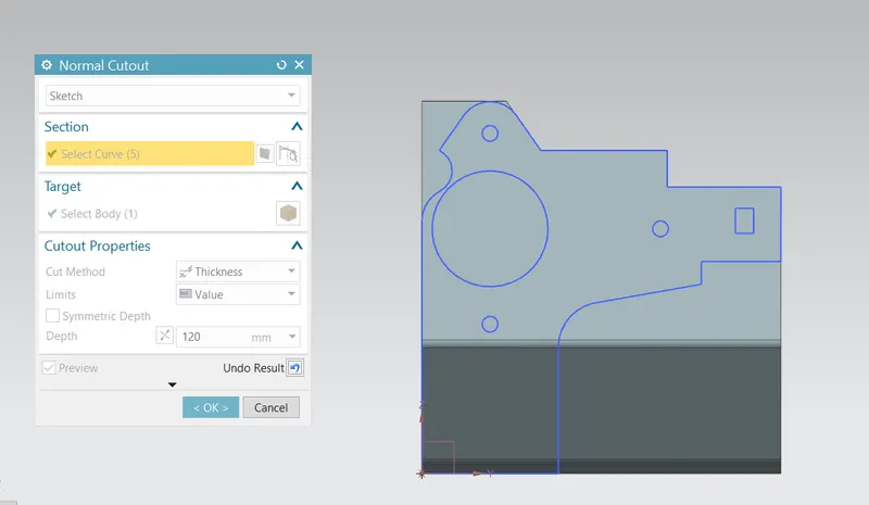
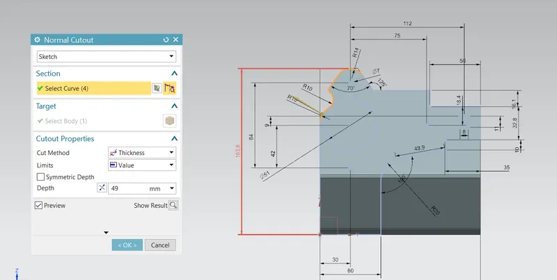
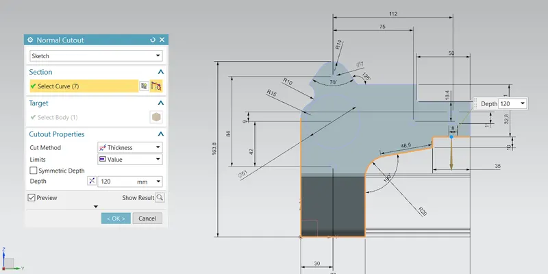
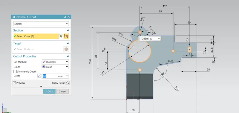
Normal cut-out function is use to cut material by projecting a sketch onto the model and then cutting perpendicular to the faces interested by the projection. For this project of bracket designing, I used this feature for cutting various section having different shapes and depth from the main sheet.
Break Corner:
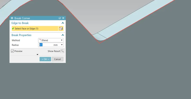
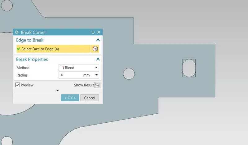
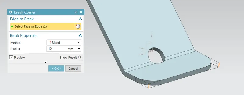
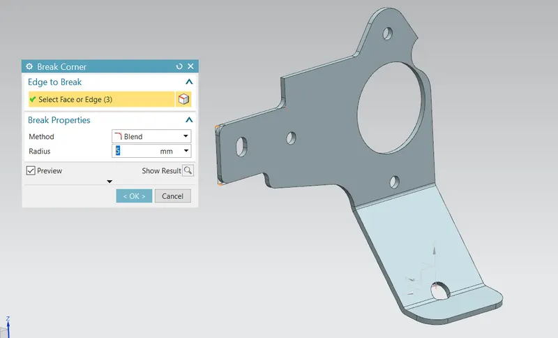
This feature is used to rounding or chamfering sharp corner of tab, flange and contours. It replaces the sharp corner with round faces making it smooth and reducing the chances of the stress concentration at the sharp corner. For this project I used break corner feature with radius shown below.
Normal cutout:
After break corner I again performed normal cutout operation 2 times selecting the curves of the base sketch on YZ plane.
Unbend:
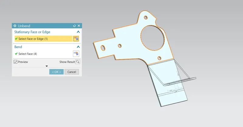
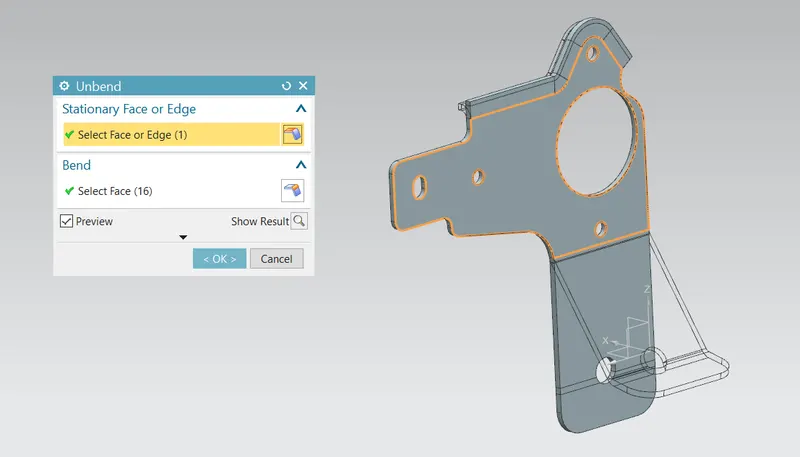
Unbend feature is one of the most powerful feature in NX. In industry we have to mark all the marking and sketch on flat sheet metal before it went to actual operations, so this unbend feature allow us to do that activity in Siemens NX software. For this project bracket design, I used this feature by selecting the face shown in figure as stationary face.
Normal cutout:
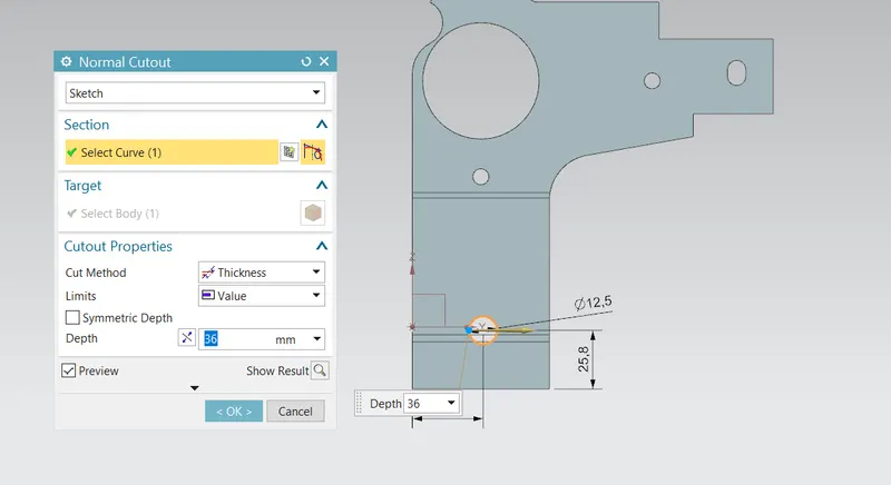
Normal cut-out function is use to cut material by projecting a sketch onto the model and then cutting perpendicular to the faces interested by the projection. First, I created circular sketch on the lower front face having radius of12.5 mm.
Rebend:
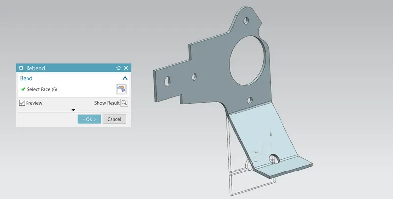
Rebend feature is used to restore the unbend feature to its previous bent state along with any features added after the unbend feature. This is done by using rebend feature and selecting all the bends carefully in order they unbended or by box selection.
Break Corner:
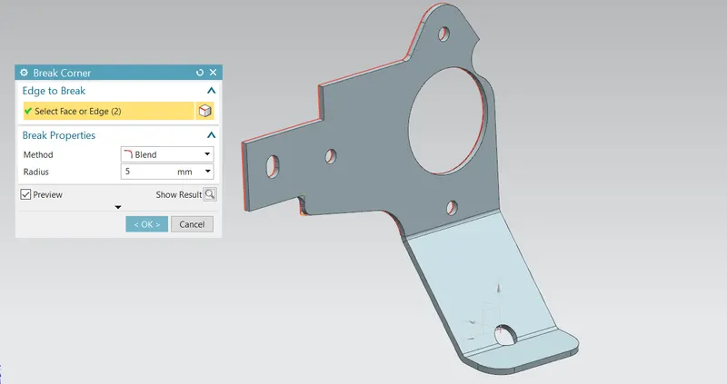
After rebend different corner having sharp edges were smoothen by using break corner feature repetitively with appropriate radius.
Advanced Flange:
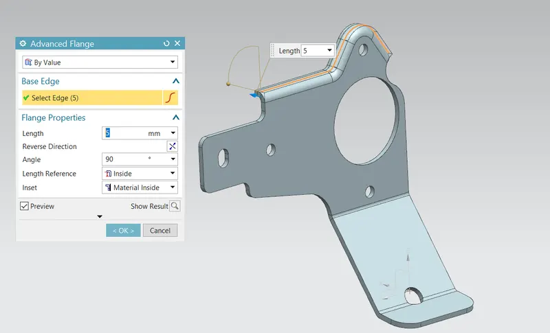
Advanced flange can create flange from any edge which can be either curved or straight profile. This allows creating a flange with a match face also. For this project of bracket designing, the advanced flange was created at the upper portion with proper parameters as shown.
Unbend:
For carrying some further operation again unbend feature was used to flatten the bracket.
Hole:
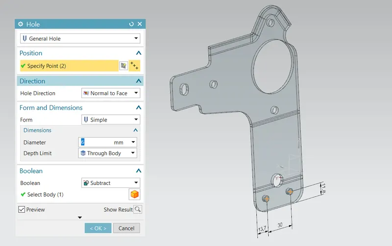
Hole feature is used to generate hole with definite parameter on sheet metal in Siemens NX. We can create different types of holes using this feature. In this project I mainly used simple through body screw hole. I first sketched 2 location points with proper dimensions and then hole feature is applied to 2 points to create final hole.
Normal cutout:
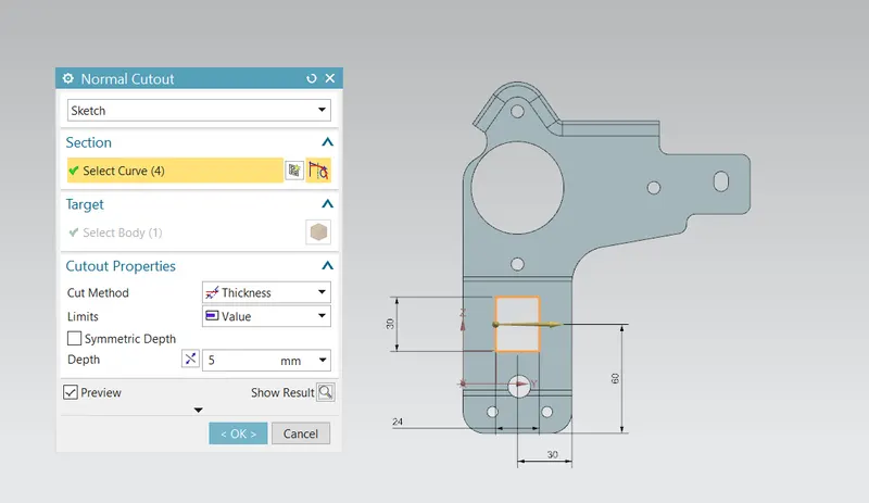
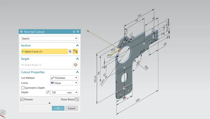
Again, normal cutout feature was used couple of times as shown below.
Advanced flange:
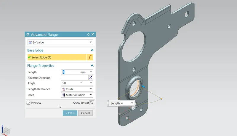
This time advanced flange was applied on the above normal cutout with parameters as shown below.
Rebend:
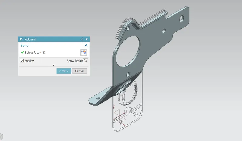
Rebend feature is used to restore the unbend feature to its previous bent state along with any features added after the unbend feature. This is done by using rebend feature and selecting all the bends carefully in order they unbended or by box selection.
Gusset:
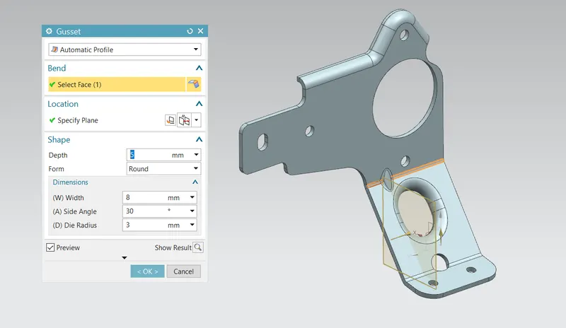
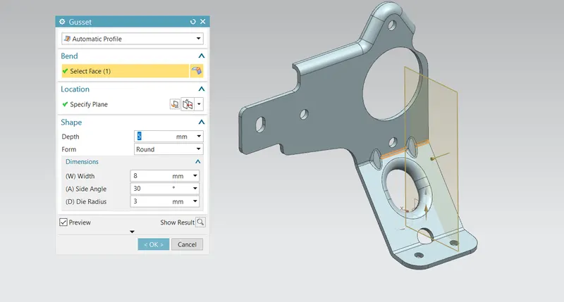
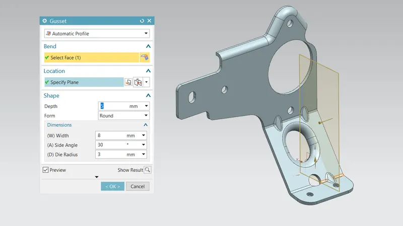
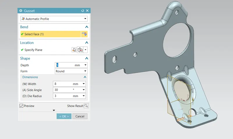
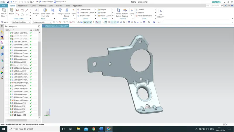
The main function of the gusset in a sheet metal component is to provide stiffness to the sheet metal part and increasing its strength. Gusset can be only employed at the bends. For this bracket, four rounded gussets were applied on the two bends as shown in below.
Flat Pattern:
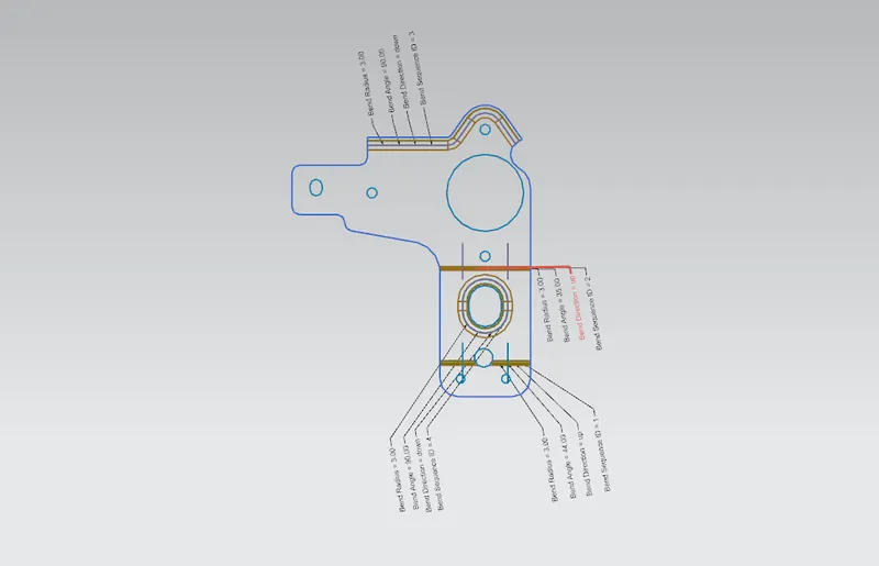
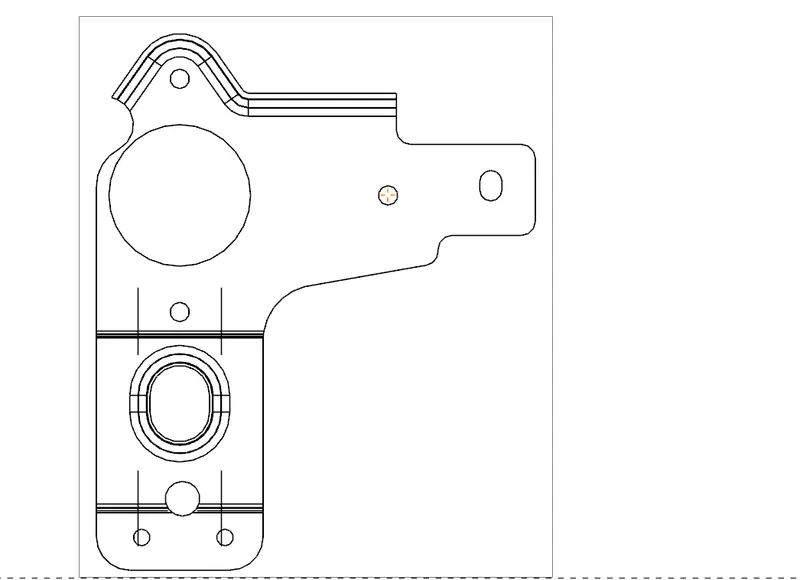
Flat pattern feature allows us to covert 3D sheet metal component into 2D form in Siemens NX software. By using this flat pattern feature we can easily avoid error like interference or collision.
Drafting:
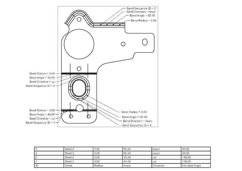
After designing 3-d model for further process of manufacturing we have to convert the entire sheet metal component into 2D form for easy interpretation. The necessary details such as annotation, callouts, bend tables can be added as per requirements. For this project of bracket design a drawing is created out of the flat pattern in 1:2 scale in A4 size.
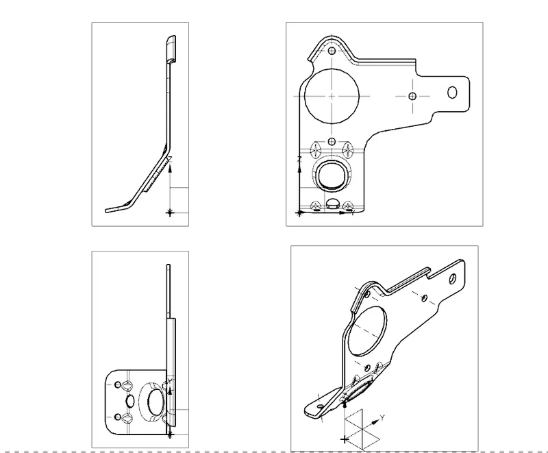
Different views of Casing:
Isometric View:

Top View:
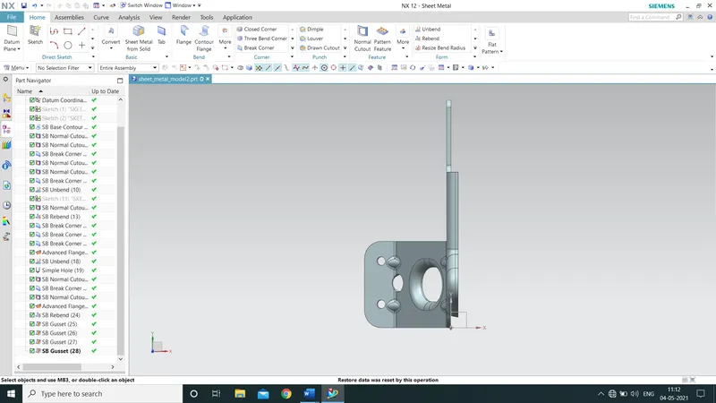
Front View:
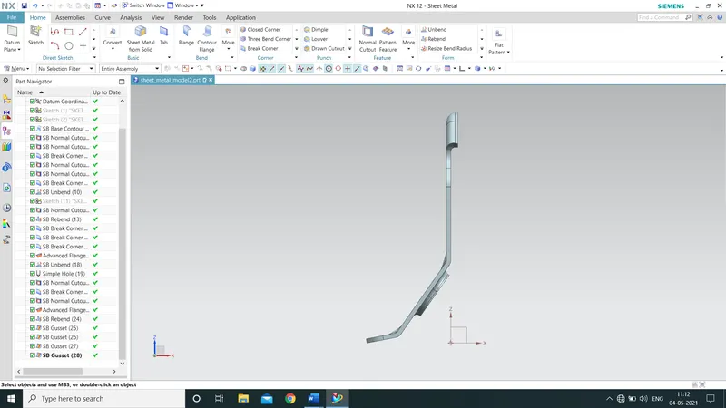
Right Hand Side View:
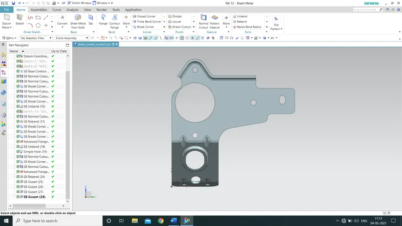
Left Hand Side View:
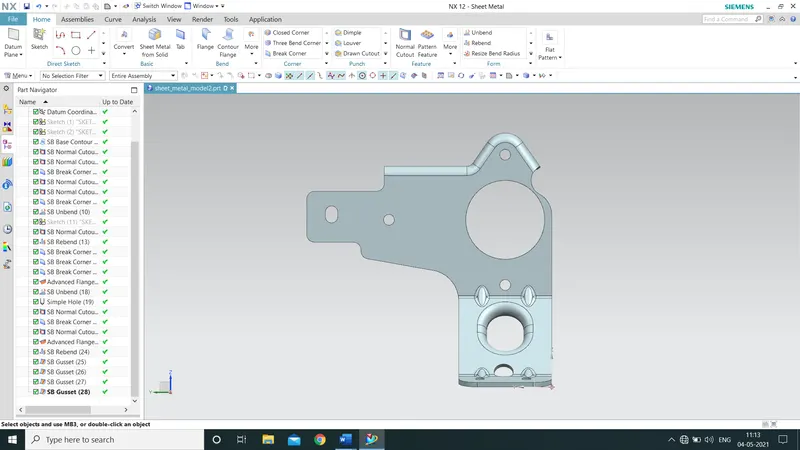
Additional View:
CONCLUSION:
- Successfully learn to design a sheet metal bracket II in industrial manner by using Siemens NX.
- Become comfortable with using environment of Siemens NX.