Advanced Sheet Metal Design Using NX Cad Challenge_7_ Metal bracket-II
Bracket design-II from 2D drawing sheet
Objective
To design a sheet metal bracket in NX12 using sheet metal application and its features.
Introduction
The bracket is usually provided to fix any parts of any fixing structure.
It also provides mechanical stability to any part and prevents movement.
Design Methodology
Commands/feature used
- Base Contour/Sketch - Closed shape
- Normal cutout/Sketch - Closed shape.
- Break corner.
- Unbend.
- Bead/Sketch-line.
- Simple screw Hole- Pick points.
- Advanced Flange
- Break Corner
- Gusset
- Rebend.
Description
Some of the features used in this bracket design are explained below
The normal cutout is provided to a bracket for two reasons, matching to surrounding file while fixing and cost-benefit design to save material without reducing the overall strength of a bracket.
Break corner is very useful to keep all sharp edges turned to blend with smooth radius and avoid easy breakage when hit with other parts in edges.
Unbend/Rebend helps to decide the sequence of sheet metal operation required for a required bracket profile like adding hole/bead after cutout in Flat surface only before bending.
The advanced flange is added to provide the strength mainly to bracket and also prevent direct contact btw target parts after fixation.
IMAGES
|
PART IMAGES/ VIEW |
FRONT VIEW | ISO VIEW | SIDE VIEW | TOP VIEW |
| BRACKET-II | 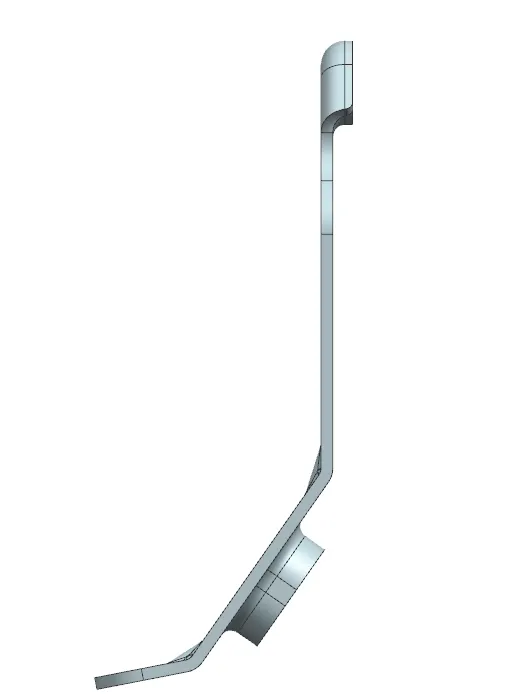 |
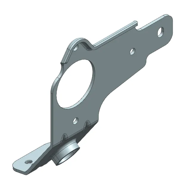 |
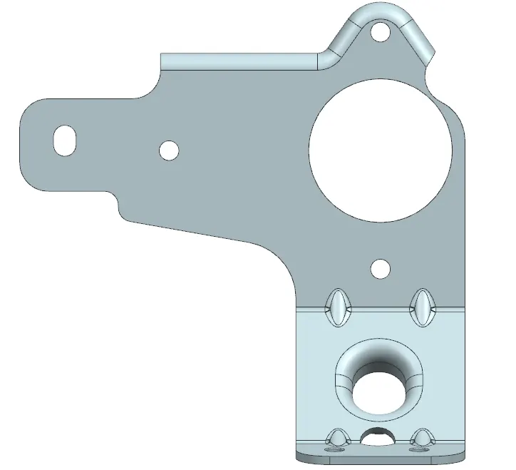 |
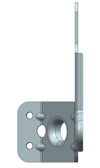 |
CONCLUSION
Thus a metal bracket is designed with various features and dimensions as 2D drawing provided.