Advanced Sheet Metal Design Using NX Cad Challenge_6_Bracket
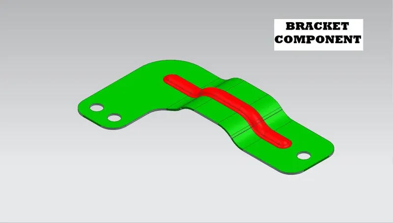
TITLE : DESIGN OF BRACKET COMPONENT IN NX SHEET METAL
OBJECTIVE:
To design and model the sheet metal bracket from a 2D Sketch in sheet metal workbench of Siemens NX CAD.
INTRODUCTION:
Sheet Metal Fabrication is the process of forming parts from a metal sheet by punching, cutting, stamping, and bending.
Sheet metal parts are known for their durability, which makes them great for end-use applications (e.g., chassis). Parts used for low volume prototypes and high-volume production runs are most cost-effective due to large initial setup and material costs.
In Sheetmetal application we can create a uniform thickness Sheetmetal parts using basic features such as flange, tabs and jogs. We can also do close corners, cut out and stiffening features. The complex sheet metal part can be designed in the solid model workbench and then we can convert it into a sheet metal part. We can also import, clean up and convert a non-sheet metal part into a valid sheet metal part. Flat pattern sheet metal data can be used for the manufacturing process. The Material parameters such as thickness, bend radii and bend relief can be easily set as default settings.
DESIGN METHODOLOGY:

DESCRIPTION:
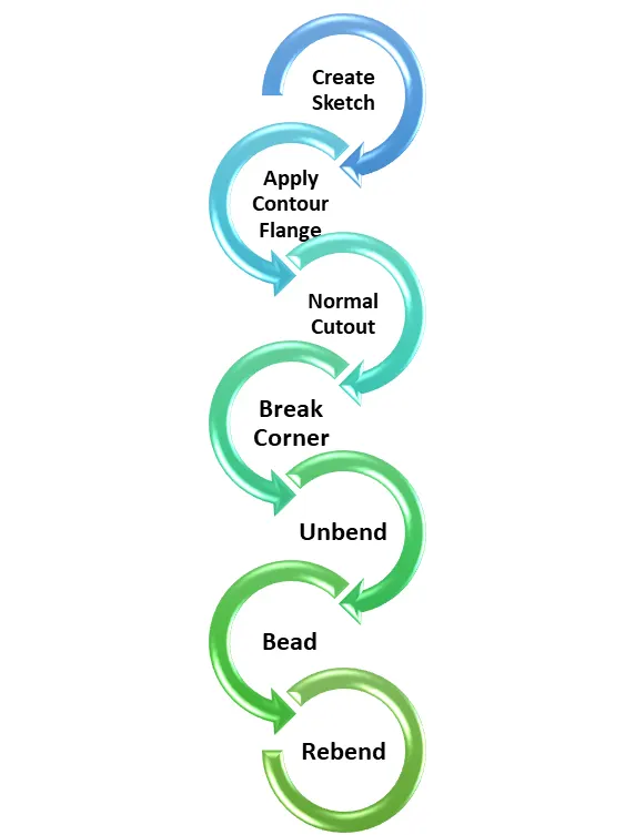
Features used for modelling bracket are contour flange, normal cutout, break corner, Bead to lift material along the contour of the sketch that simulates a stamping stool, Bend to bend the material, Flange to create flanges, Unbend to unbend the metal sheet, Holes for adding holes, dimple to create a deformation on the sheet metal, and Rebend.
Create Sketch:
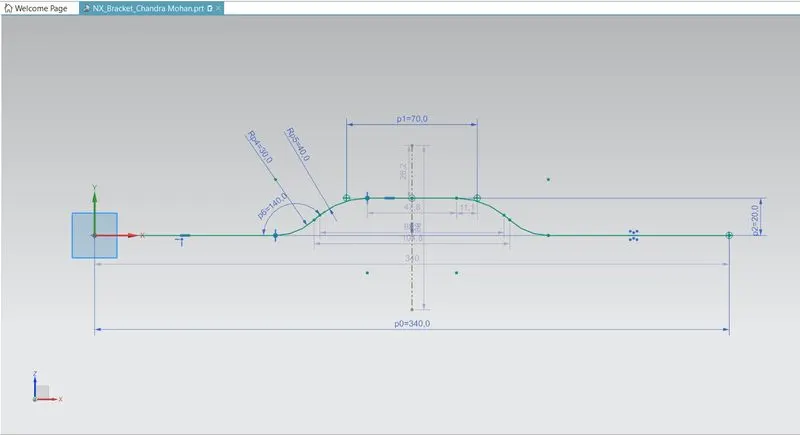
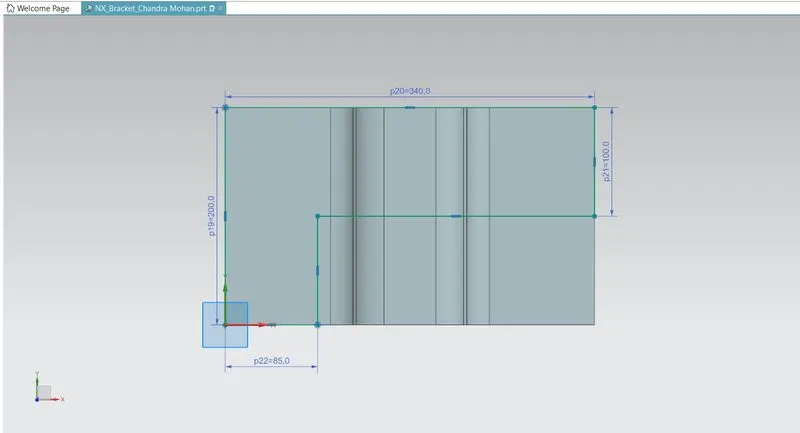
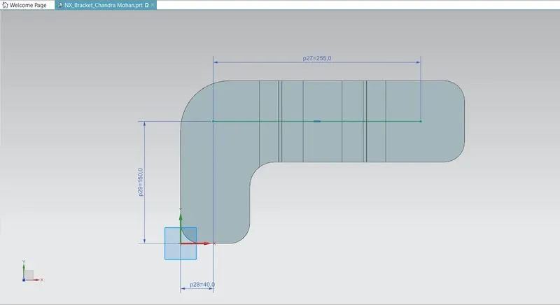
The Sketch is creating in the XY Plane, represent the required dimensions for the sketch.
Contour Flange:
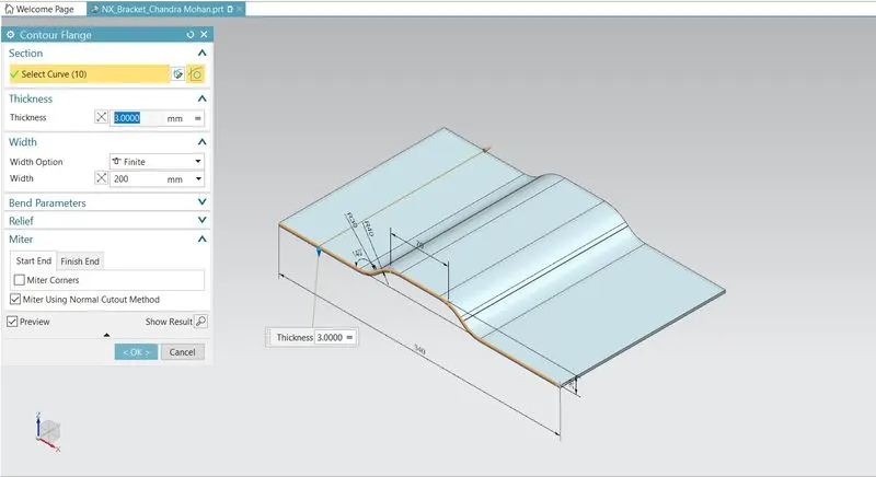
You define a single contour flange by selecting an open profile. Inventor can create contour flanges along an edge or edge loop. Inventor previews the flange material thickness along the selected profile and toward the material of the selected edge. However, you can reverse the thickness direction.
Use the contour flange command and select the sketch as shown above,determine the thickness as 3mm for the flange.
Normal Cutout:
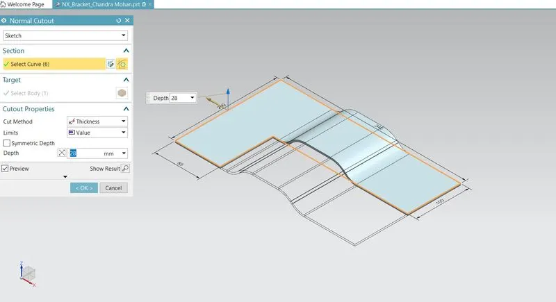
This command is used to cut the material by projecting the sketch onto the model and then cutting perpendicular to the faces intersected by the projection. The skecth is required to use the normal cutout feature. So, we are creating sketch in XY Plane.
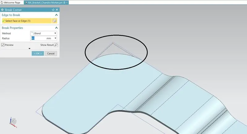
Break Corner:
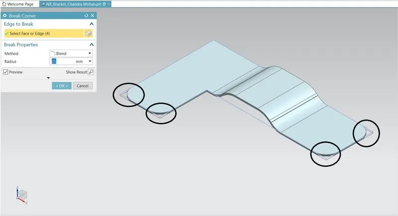
This command is used to round or chamfers the sharp corner of a tab or flange.
Corner Radius = 25mm
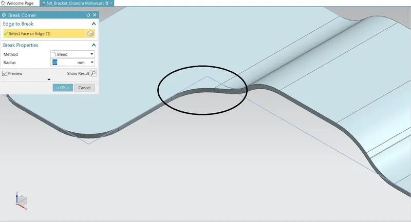
Corner Radius = 30mm
Corner Radius = 60mm
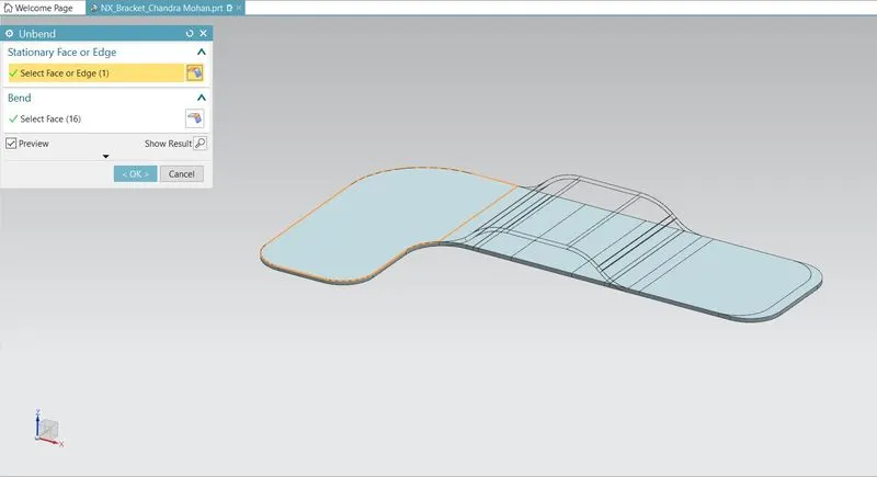
Unbend:
This command is used to unbend the sheet metal. The punching operation can be performed only by unbending the sheet metal.
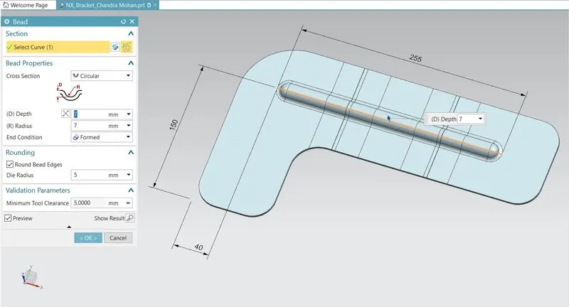
Bead:
This feature that we will go over in this post is the Bead. The Bead is like a raised rib in the sheet metal panel. It requires that you have at least one sheet metal panel in the active part as well as an open or closed loop sketch.
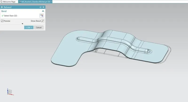
Rebend:
Rebend feature is used to get the original bend shape after performing forming operations like a dimple, bead.
After finishing all these operations, then the sheet metal part should to rebend to check the DFM (Design for Manufacturing) process.
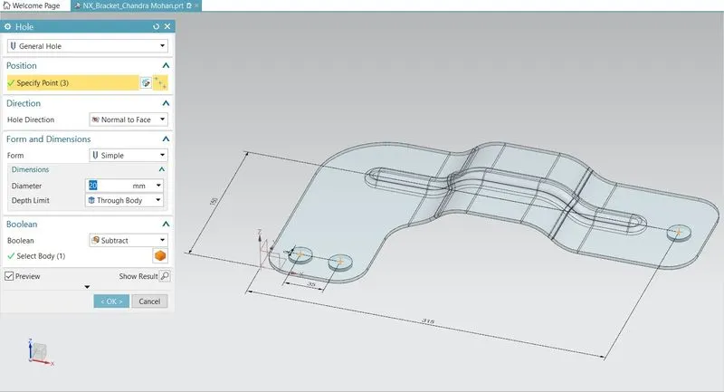
Holes:
Holes are added to provide alignment to enclosure. NX provides whole feature has options like general type, counterbore, countersink, etc. Position, Diameter and depth are important inputs to apply hole to a body.
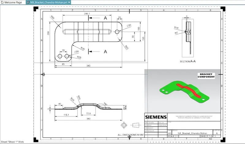
DRAFTING (Drawing Sheet)
It is refers to creating technical drawing that communicate about dimensions, view of component geometry and other features that performed over part in 2D or 3D. The draft of drawing is prepared which include annotation, dimension, relations, etc. which helps to a person from manufacturing or production department about component.
Designed a Bracket Component in Siemens NX Sheet Metal Application
Model with Feature Tree:
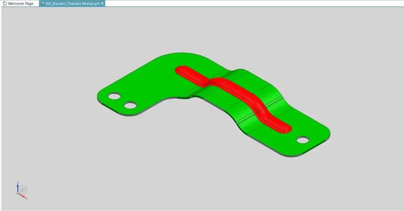
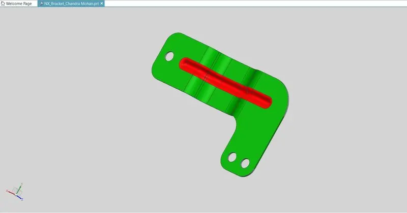
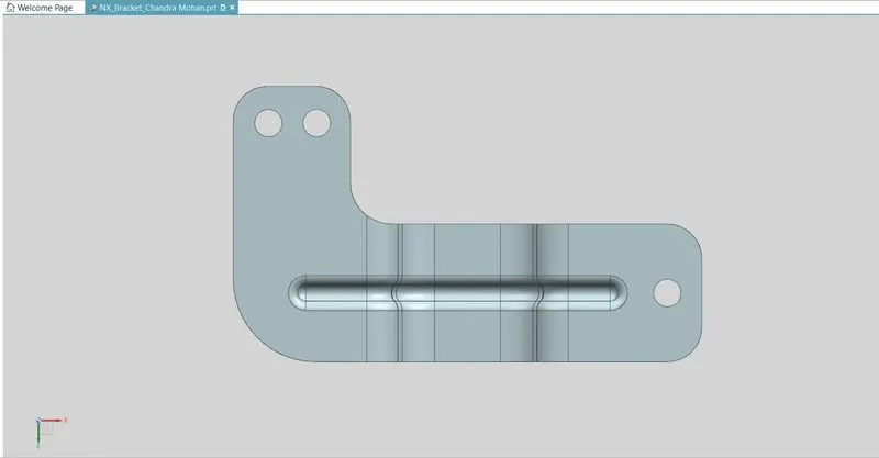
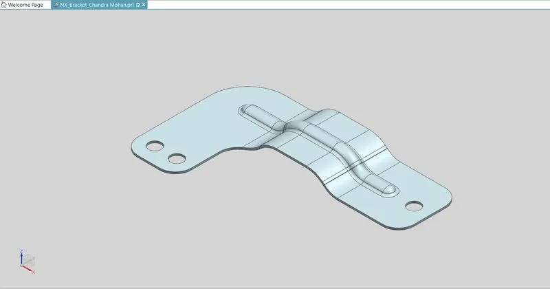
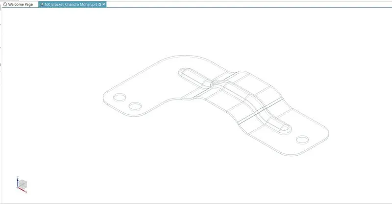
Bracket Component
(MODEL VIEWS)
Front View:
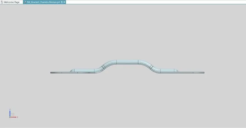
Side View:
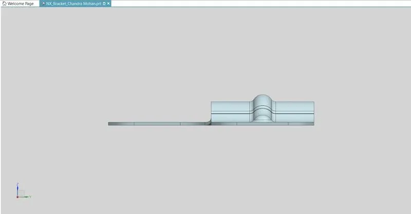
Top View:
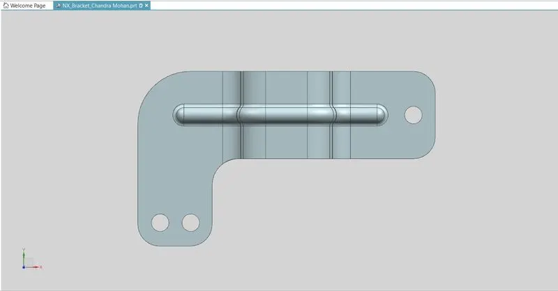
Bottom View:
Isometric View:
Wireframe View:
CONCLUSION:
The sheet metal Recommended workflow to create Bracket Component or angles is successfully completed in NX Cad.