Advanced Sheet Metal Design Using NX Cad Challenge_6_Bracket
TITLE OF THE PROJECT :- BRACKET DESIGNING USING NX CAD
Objective :- To create metal bracket from given 2D drawing.
INTRODUCTION
- For creating metal bracket from 2D drawing i have used various tools in NX Cad.
- I have used tools such as contour flange, normal cutout, break corner, unbend, rebend, bead.
DESIGN METHODOLOGY
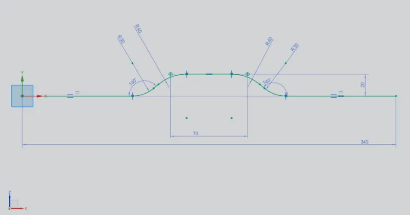
1. Draw a sketch on XZ datum plane.
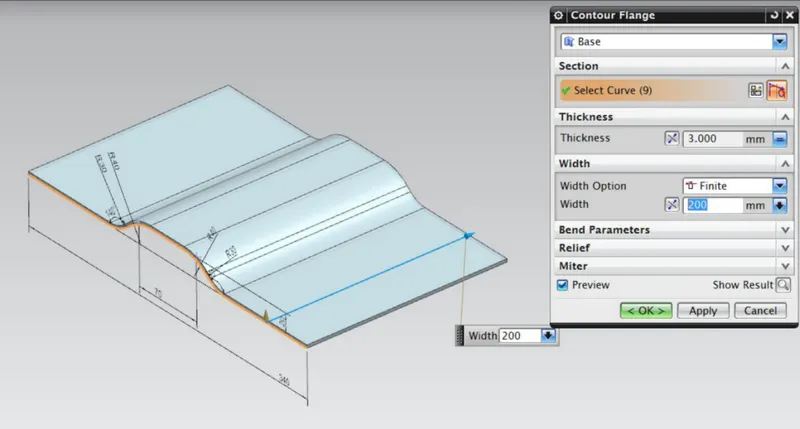
2. Use contour flange to create a solid body.
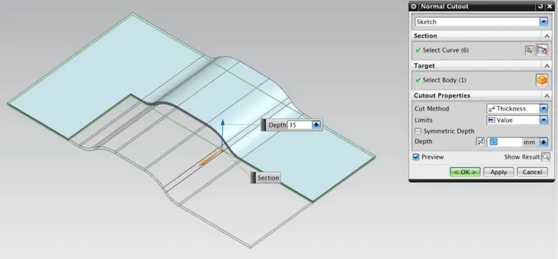
3. Use normal cutout to get the desired solid body.
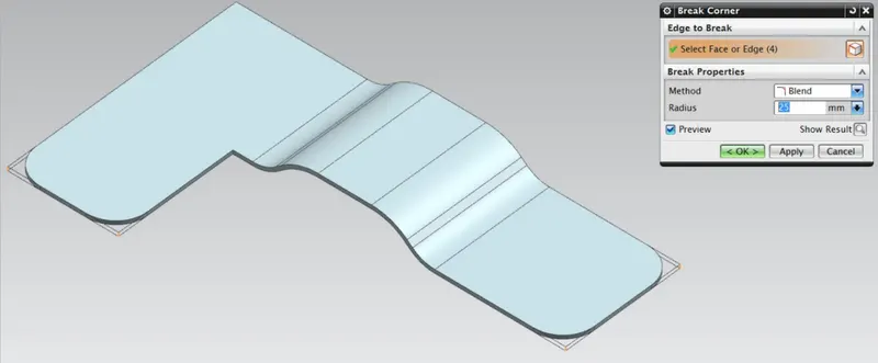
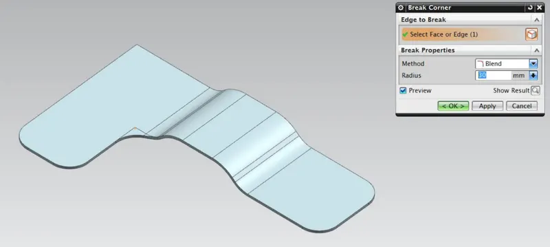
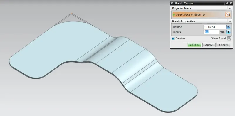
4. Use break corner to Blend the sharp edges.
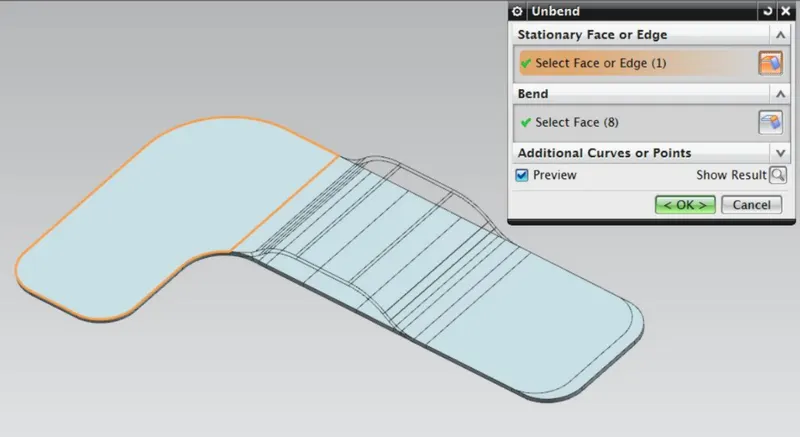
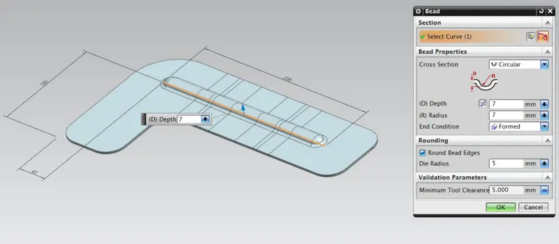
5. Use unbend form a bead on the solid body.
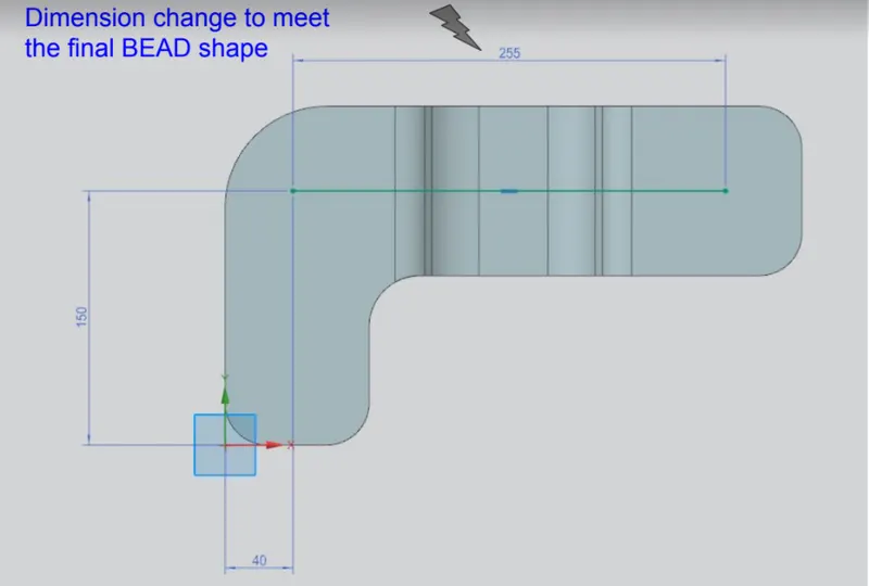
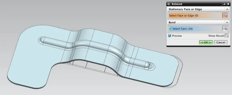
6. Use rebend to bring solid body back to desired shape.
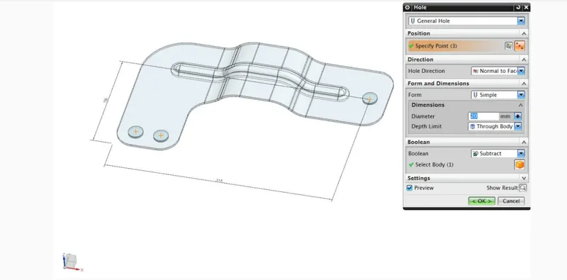
7. Use Hole to punch a general hole through the solid body.
DESCRIPTION :-
- CONTOUR FLANGE :- It is created by extending the sketch on its representative axis with the thickness as required from the base.
- Normal Cutout :- It is used to cut or create a gap in the sketch.
- Break Corner :- It is used to make the comers blend with some self dimensioned radius in order to make corners smooth.
- Unbend :- It is used for Unbending corners of the body.
- Bead :- It is used to create a contour shape according to the sketch in the required direction with required punch/die radius.
- Rebend :- It is used for bending corners of the unbend body.
- Hole :- A Hole feature is used to create holes on the model.
IMAGES
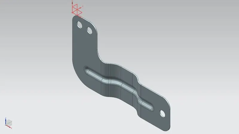
ISOMETRIC VIEW
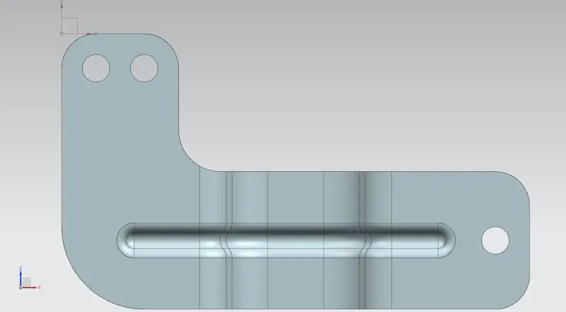
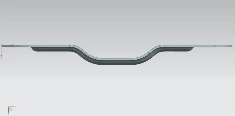
FRONT VIEW
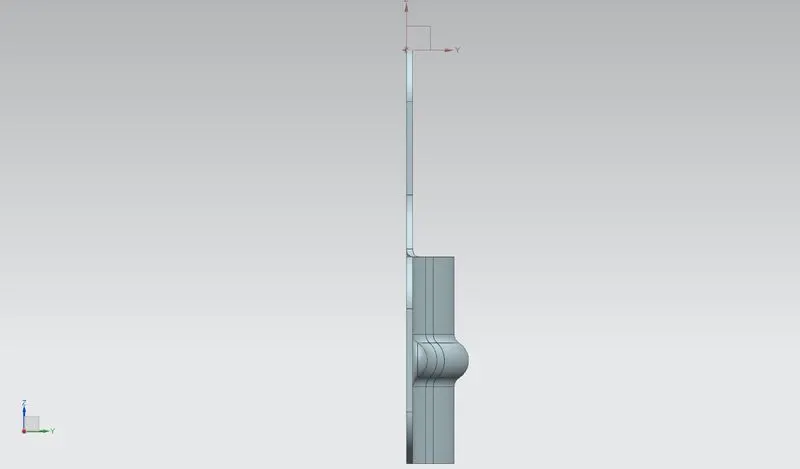
SIDE VIEW
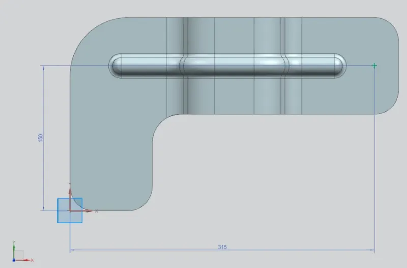
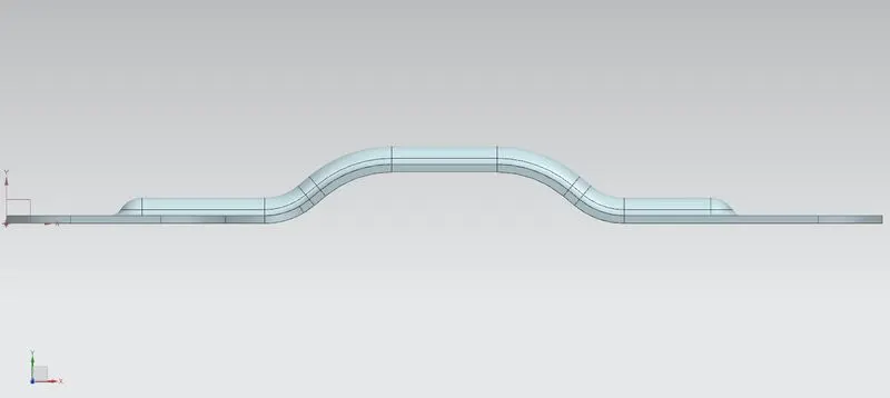
TOP VIEW
BOTTOM VIEW
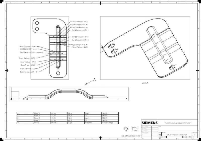
DRAWING SHEET
CONCLUSION :- Thus we have successfully designed metal bracket using 2D drawing Using NX Cad.