Advanced Sheet Metal Design Using NX Cad Challenge_6_Bracket
TITLE: SHEET METAL BRACKET DESIGN USING NX CAD
OBJECTIVE: In this project we are going to design a Bracket in NX using Sheet Metal application.
INTRODUCTION: Sheet metal refers to metal that has a high surface area to volume ratio. Sheet metal work stock, used for sheet metal processes is usually formed by rolling and comes in coils.
Bracket – An overhanging member that projects from a structure (such as a wall) and usually designed to support a vertical load or to strengthen an angle.
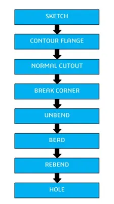
DESIGN METHODOLOGY: The following design methodology is used for design a bracket.
DESCRIPTION:
SKETCH: It is the 2D representation of the model with respect to the plane or view.
CONTOUR FLANGE: Creates a base feature by extruding sketch along a vector, or adds material by sweeping a sketch along an edge or chain of edges.
NORMAL CUTOUT: It cuts material by projecting a sketch onto the model and them cutting perpendicular to the faces intersected by the projection.
BREAK CORNER: Rounds or chamfers a sharp corner of a tab or flange.
UNBEND: Flattens a bend and the material adjacent to the bend.
BEAD: Lifts material along the contour of a sketch that simulates a stamping tool.
REBEND: Restores an unbend feature to its previous bent state, along with any features added after the unbend feature.
HOLE: Adds a hole to one or more solid bodies in a part or assembly.
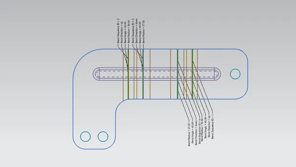
FLAT PATTERN: Creates a flat pattern from the formed sheet metal part.
STANDARD VIEWS OF MODEL:
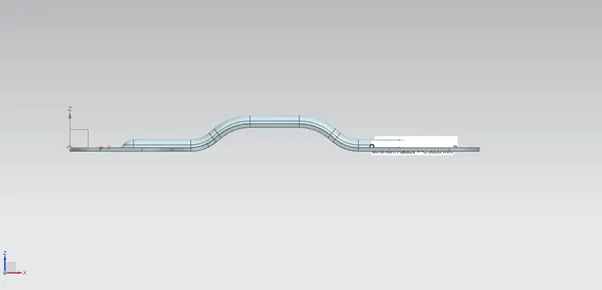
FRONT VIEW:
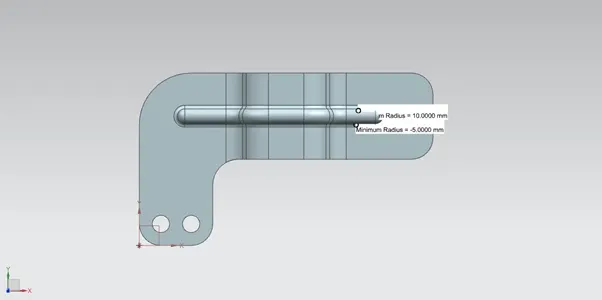
TOP VIEW:
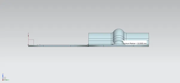
SIDE VIEW:
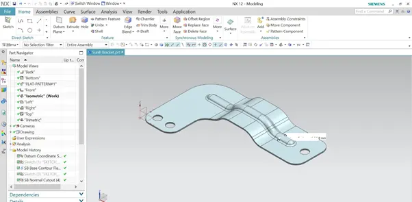
ISOMETRIC VIEW:
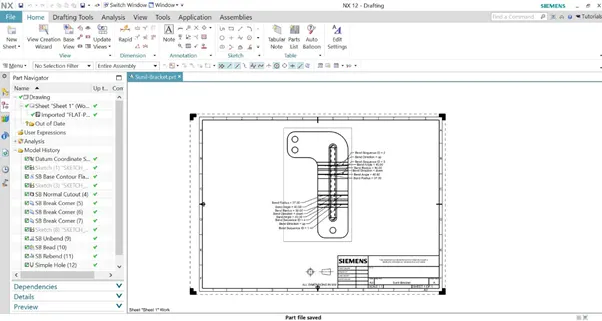
DRAFTING: Drafting is a term that refers to creating technical drawings that communicate how something is constructed or functions.
CONCULSION: Successfully designed a Sheet metal Bracket design using siemens NX Sheet metal workbench.