Advanced Sheet Metal Design Using NX Cad Challenge_6_Bracket
TITLE :
To develope the bracket with the help of 2D drafted drawing.
OBJECTIVE :
To desing the Bracket using NX CAD sheet metal application.
INTRODUCTION :
What is Drafting?
Drafting is the process of creating technical drawings or plans that are used to communicate how something is to be constructed, manufactured, or assembled. These detailed drawings often include dimensions, materials, and other specifications. Drafting is commonly used in fields like architecture, engineering, and manufacturing to create blueprints or schematics. In process Oriented feild we majorly using Schematic to understand the process of an application. Common Schematic diagrams are Pipe and Instrumentation diagram (PID) , Single line Diagram (SLD), etc.. In Material processing unit we commonly detailed the component like its dimension's, specification, material Grade, Quality checking, Tolerance, Bill of materials, Revision tracking, etc..
Sheet metal drafting is important because it plays a crucial role in the design, fabrication, and assembly of metal components. In industries like manufacturing, aerospace, automotive, and construction, where sheet metal is widely used, precise drafting is essential for efficient production and quality control.
DESIGN METHODOLOGY :
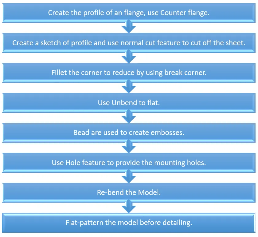
DESCRIPTION :
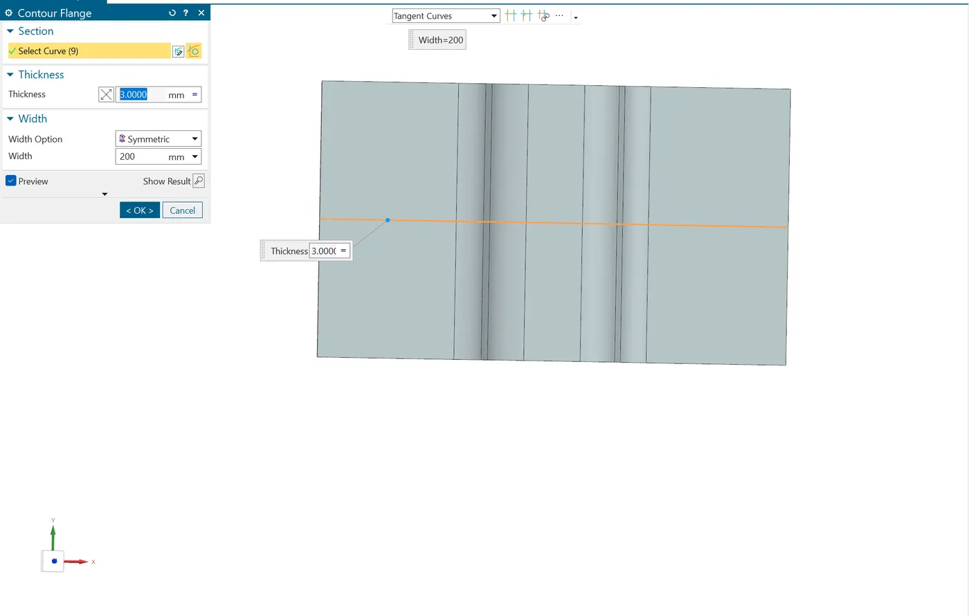
- COUNTER FLANGE : Draw the profile and dimensioned it by using the drawing and use the counter flange command to create the base flange.
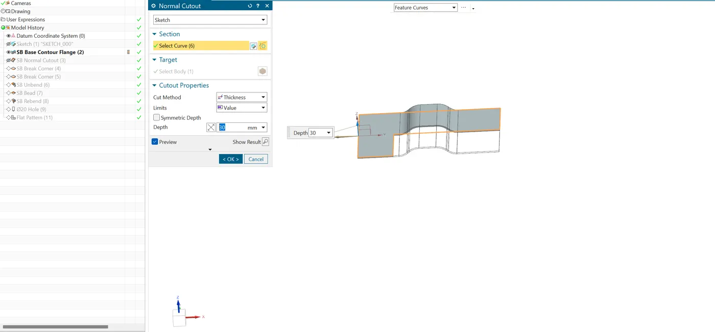
- NORMAL CUTOUT : Normal cutouts are features that allow you to remove material from the sheet metal part.
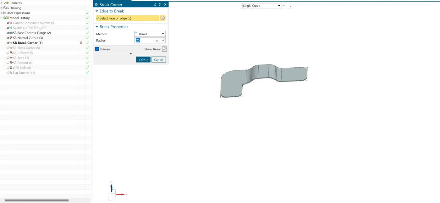
- BREAK CORNER : Break Corner feature is used to modify or round the edges of a sheet metal part, typically by applying a chamfer or fillet. This feature is essential for improving manufacturability and preventing sharp edges that could cause safety issues or material stress.
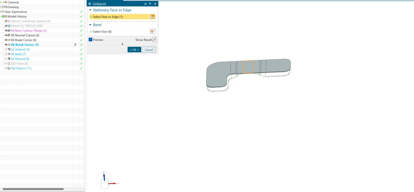
- UNBEND : Unbend can used to preview the Blank state of the Component. After selecting the stationary face, you'll be prompted to select the bends that you want to unbend.
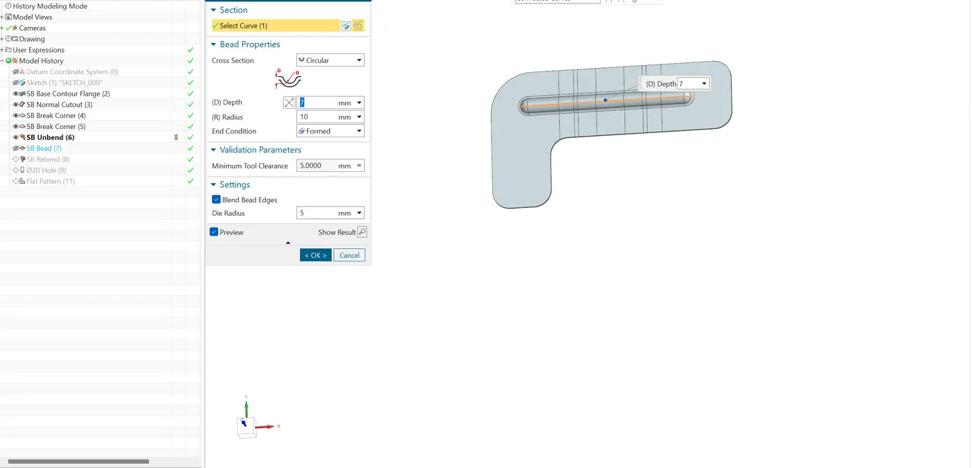
- BEAD : It is used to create the stiffning surface on the flange by pop up the surface by using sketch profile.
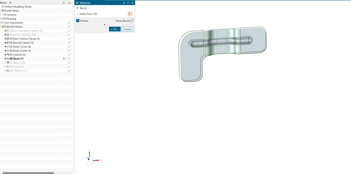
- RE-BEND : It is used to return a previously unbent or flat sheet metal part back to its original bent state.
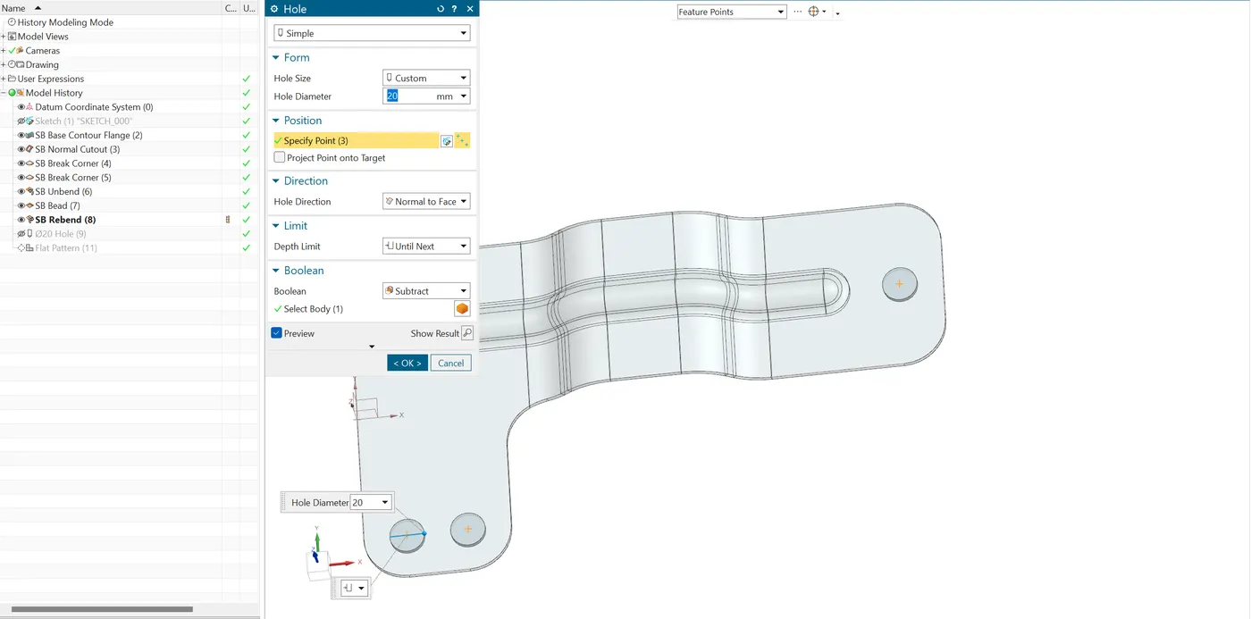
- HOLE : This command allows you to define hole size, shape, depth, and other parameters, making it essential for adding features like mounting holes, access points, or drainage holes.
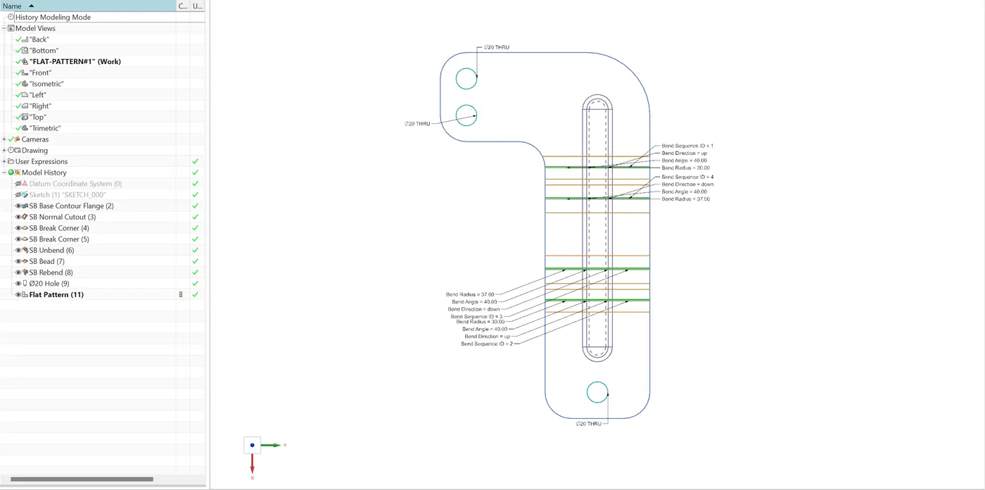
- FLAT PATTERN : It generate the 3D model into 2D blank is essential for manufacturing processes like laser cutting, CNC machining, or stamping.
CONCLUSION :
We created the Bracket design by using Counter Flange feature in NX cad.