Advanced Sheet Metal Design Using NX Cad Challenge_6_Bracket
BRACKET:
Objective:
To design bracket using sheetmetal workbench of NX CAD
Introduction:
Generally sheetmetal thickness range varies from 0.4mm to 6mm then it is called has sheetmetal,The sheet metal
modelling is used for designing the models like the battery cases,casing for the radiators and also for creating the models that have rectangular or the square shape or the L brackets etc these kind of objects are more convinent for designing the objects.
If the thickness is less than 0.4mm then it is called has foil.
If the thickness is more tham 6mm then it is called has plate.
Design Methodology:

Procedure:
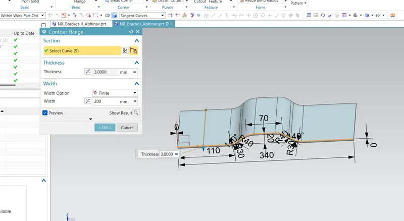
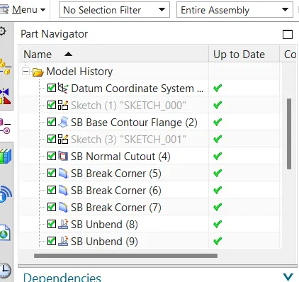
First we create a sketch for countour flange creation.the contour flange command is clicked to create the flange of given length.and then we select the sketch and give the thickness with proper direction.
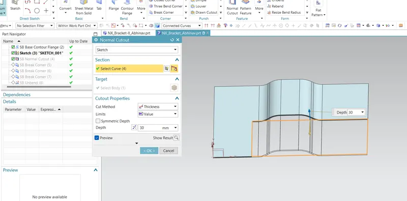
then we remove some portion of part using normal cut tool.the remove portion draw using sketch option anf apply the normal cut to the sketch with deapth value and direction.
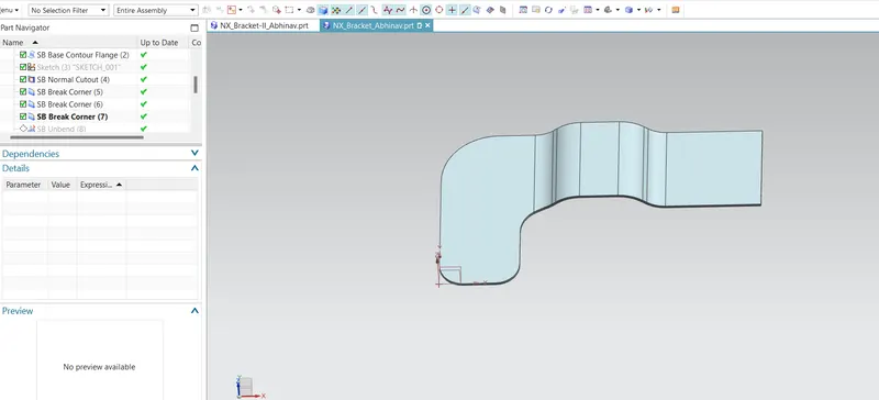
Corner breake option is used to break the sharp edges of sheetmetal, corner breake tool added with a radius.
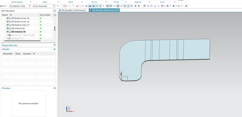
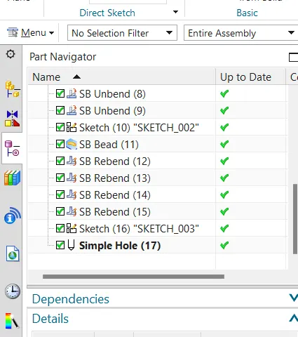
the part is unbend first to create the bead on it.to unbend the part first we have select the unbend command and then select the flat face first and then select all the body bend faces.
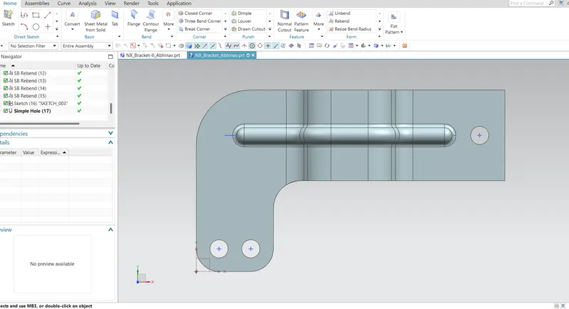
Bead is selected to create it firstly the sketch is created on flat surface and then we give the thickness and diameter to it. finally we give proper direction to it and click ok to get the bead
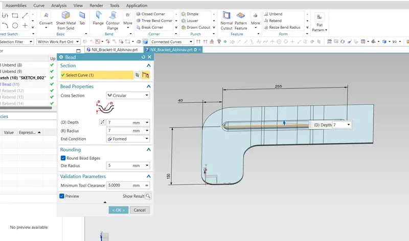
Rebend command used to recreate its original benst shape.
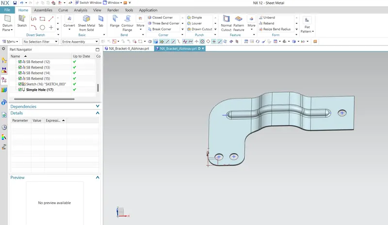
Hole command is selected to create the hole firstly we create the point and then we specify the size and depth.we rebend the bend which are created
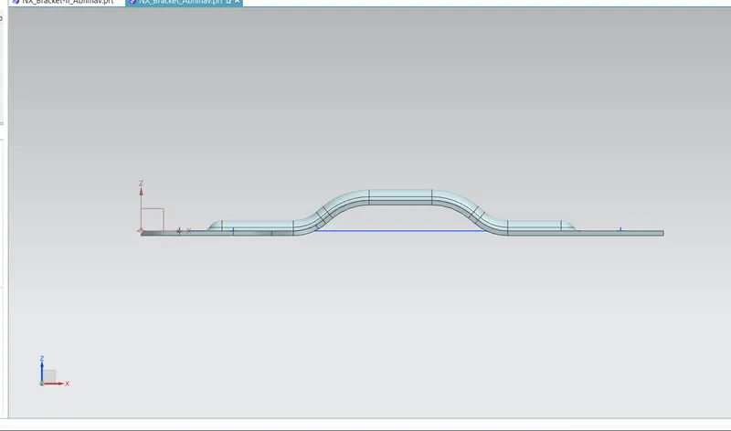
Drafting of bracket
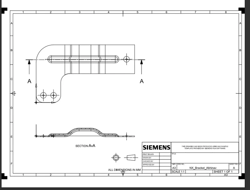
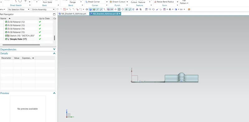
Views
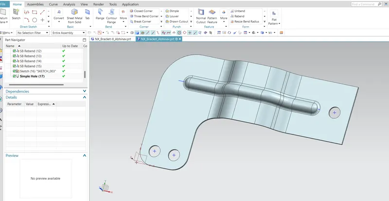
Conclusion:
The sheet metal bracket is created as per the procedure they given in the question