Advanced Sheet Metal Design Using NX Cad Challenge_6_Bracket
Designing of Bracket
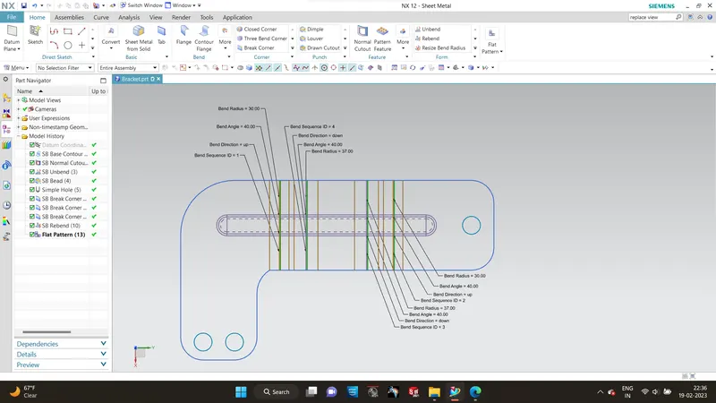
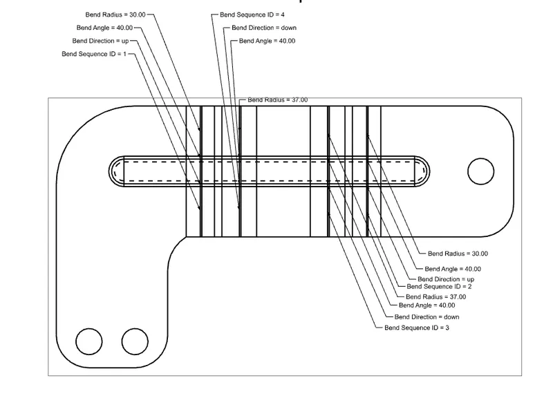
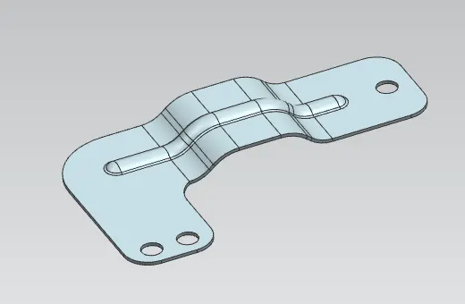
Objective: To create the Bracket part from the given 2d drawing.
Design methodology / approach:
- Start with the major sketch of the part using the contour flange feature to create the part directly wth the bend in the sketch.
- Use normal cut-out to trim and get our desired shape
- Eliminate the sharp corner using the break corner.
- unbend the bracket and add the center bead, refer to the drawing for the dimensions.
- Create the holes and rebend, your component is finished.
Feature Information:
Use the Contour Flange command to create a flange by extruding a sketch along a vector, or by sweeping a sketch along an edge or chain of edges. NX adds bends automatically using the default bend radius value. To use a different bend radius value, draw arcs in the section, or change the default bend radius value.
Use the Break Corner command to round or chamfer sharp corners of a tab or flange.
Use the Unbend command to unbend a portion of the part to construct cutout features, hole features, or deform features across a bend. You can later reform the bend to represent the true formed state of the model.
Use the Bead command to lift material along the contour of a sketch that simulates a stamping tool. Beads can also be created to stiffen sheet metal parts.
Use the Rebend command to return an unbend feature to its previous bent state. Any features added after the unbend operation are properly repositioned during the rebend operation.
Use the Normal Cutout command to cut material by projecting a sketch onto the model and then cutting perpendicular to the faces intersected by the projection.
Use the Flat Pattern command to create a 2D representation of the flattened 3D sheet metal part.
You can:
- Create a flat pattern from a formed sheet metal body or from flat solids.
- Control orientation of the Flat Pattern view for the upward face having non-linear edges. To do this, you need to specify a CSYS while defining the orientation.
- Represent holes smaller than or equal to a specified diameter value as countermarks in the flat pattern view. This is useful when holes need a different manufacturing process.
- Create an associative flat pattern fixed at the current timestamp. This helps you create a flat pattern view at the intermediate stage of the part design.
- Edit the bend properties, such as bend sequence and bend names, using the Bend List command after making the Flat Pattern view as the active view.
Get the lengths of the exterior boundary and interior cutouts of a flat pattern.
VIEWS:
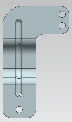
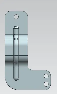
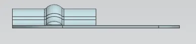

Flat Pattern and Drawing: