Advanced Sheet Metal Design Using NX Cad Challenge_6_Bracket
Sheet Metal Bracket Design Using NX CAD
Objective
The aim of this project to design a sheet metal bracket with some advanced features using NX Sheet Metal Application.
Introduction:-
Unigraphics NX (also known as Siemens nx) is an advanced High-end CAD/CAM/CAE software package originally developed by UGS Corporation, But since 2007 it is owned by Siemens PLM Software. It is used, among other tasks, for Design ,Engineering analysis ,Manufacturing finished design by using included machining modules.
NX Sheet Metal provides a set of tools within the NX design environment that allows for simple and fast design of sheet metal parts, dependent on their material and manufacturing process, the most common of which is straight brake sheet metal forming.
Design Methodolgy
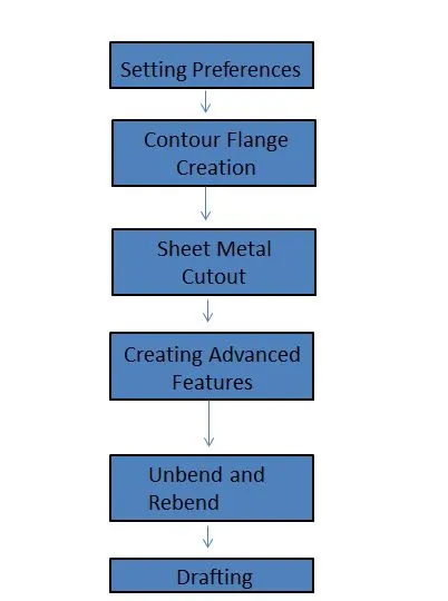
DESCRIPTION
- Setting Preferences
The First step in Sheet Metal Modeling isto validate the seet metal preferences and modifying the global values as per the project requirement.
Creating Contour Flange
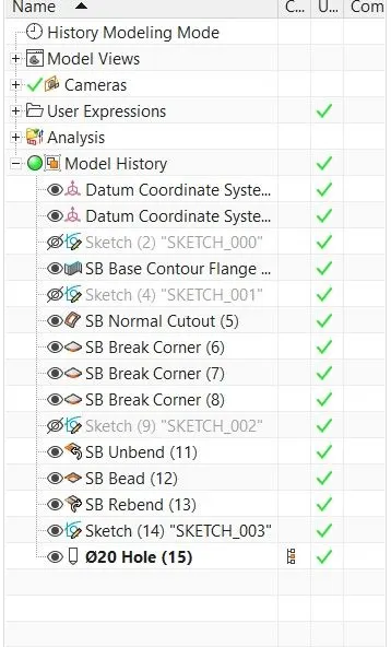
- The Next Step is to create a contour Flange.
- A New Sketch is created in 2D Plane and the this curve is used to create a flange with desired length.
Sheet Metal Cutout
- The Next phase is to cut part of the sheet metal to desired shape. Normal Cutout is used which cuts the sheet metal model through projection of Sketch onto the model and cutting perepndicular to faces.
- After a 2D sketch is created it is then used to cutout the sheet metal part.
Creating Advanced Features
- The Next Phase is to break the sharp corners to allow easy faciltaion of tool path.
- The Sharp corners are applied with Break Corners which blends the model to its given radius.
- Then the sheet metal model is prepared for adding beads and holes.
Unbend and Rebend
- Then the Sheet Metal model is unbend using a stationary face
- The Main reason to add Beads after unbend option is to have smooth projection bead surface accross the bending faces.
- A 2D sketch is created for Bead profile and it is used to lift the material that simulates the stamping tool.
- A Circular Bead is desired for this model and the depth, radius and end condition are defined.
- The Next Step is to Add a simple Hole by specfying the points at three positions.
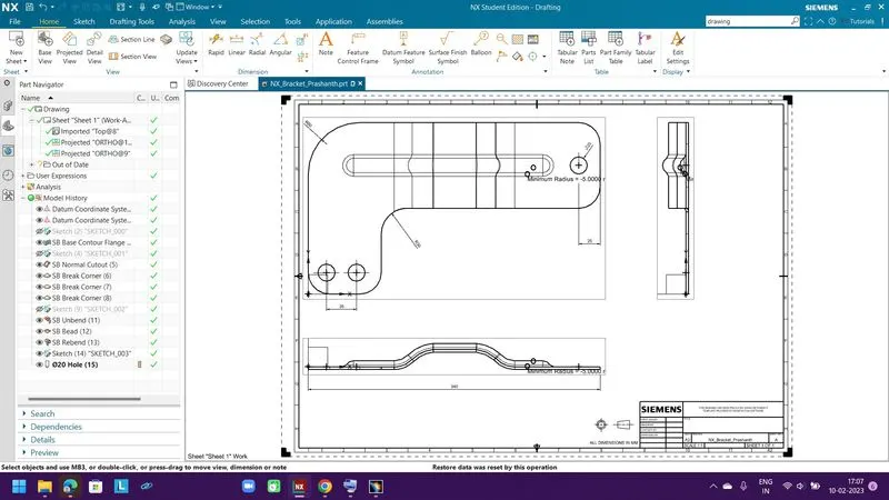
- Then the model is exported to Drawing.
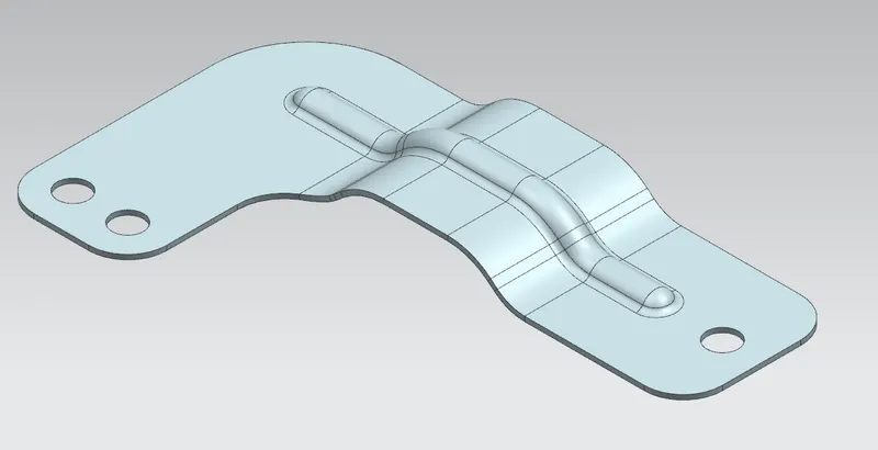
Various Model views of the created sheet metal bracket is shown below.
1 -TOP VIEW of part .
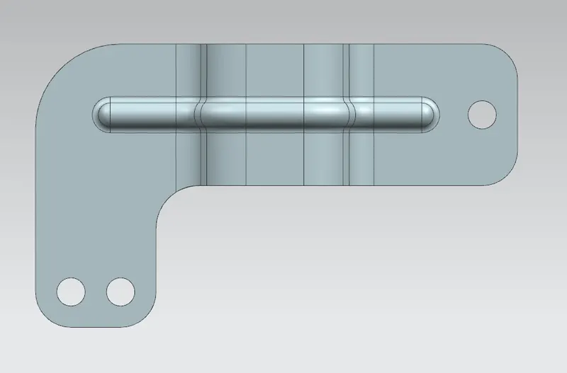
2 -FRONT VIEW of part .
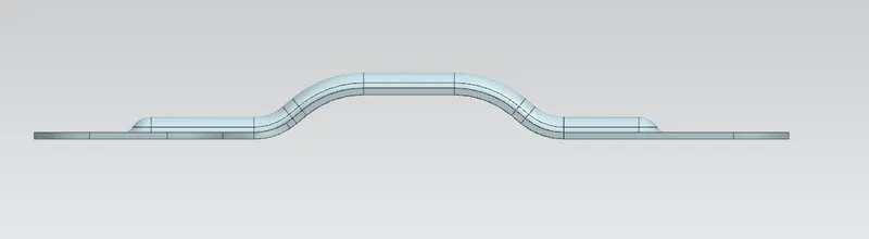
3 - SIDE VIEW of part .
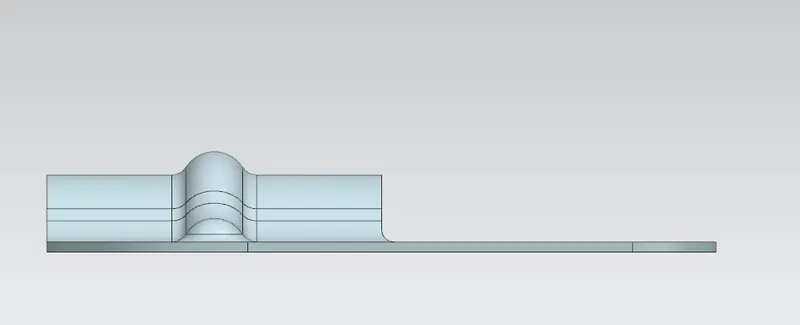
4 - ISOMETRIC VIEW of part .
5 - FEATURE TREE of model .
Conclusion
Thus advanced features in Siemens NX Sheet Metal Appliaction is grasped through simple Sheet Metal bracket design with a structured design methodolgy.