Advanced Sheet Metal Design Using NX Cad Challenge_6_Bracket
Sheet Metal Design of Metal Bracket
Objective
The main objective of the report is to show the sheet metal modeling of the metal bracket.
Introduction
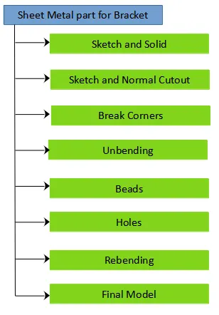
Sheet metal design is the process of making components from thin metal sheets by bending, cutting and fastening. Sheet metal design has varied application. The basics of sheet metal design are learnt and applied in creation of a Metal Bracket. The following steps were undertaking while designing the Sheet Metal Casing:
1. Creation of a sketch in front view and solid body
2. Creation of sketch in top view and Normal Cutout
3. Creation of Break Corner
4. Unbend the sheet metal
5. Sketches for holes and beads
6. Creation of holes and beads
7. Rebend the Component
8. Depiction of Local Radius
Design Methodology
Features
Sketches, Normal Cutout, Bend, Flange, Simple Screw Hole, Bead, Unbend and Rebend
Description
Create a line sketch in the XZ plane using the given dimensions and using base Contour Flange command create the sheet metal body of width 200 mm. Create another sketch on the XY plane in the shape of "L" for the given dimensions and cut the sheet metal using Normal Cutout command to obtain the initial shape of the bracket. Using Break Corner command smoothen the required sharp edges. Unbend all the bent surfaces. Create a line on the longer side of the bracket and create the bead of depth 7 mm and radius 7 mm and rounding parameters of 5 mm. Create another sketch and place point on required position and using Hole command create simple holes of diameter of 20 mm . Rebend all the surface to finish the Metal Bracket.
Views
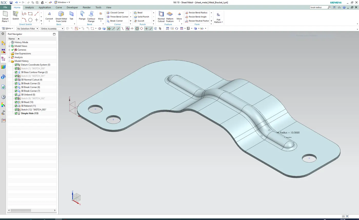
1. Isometric View
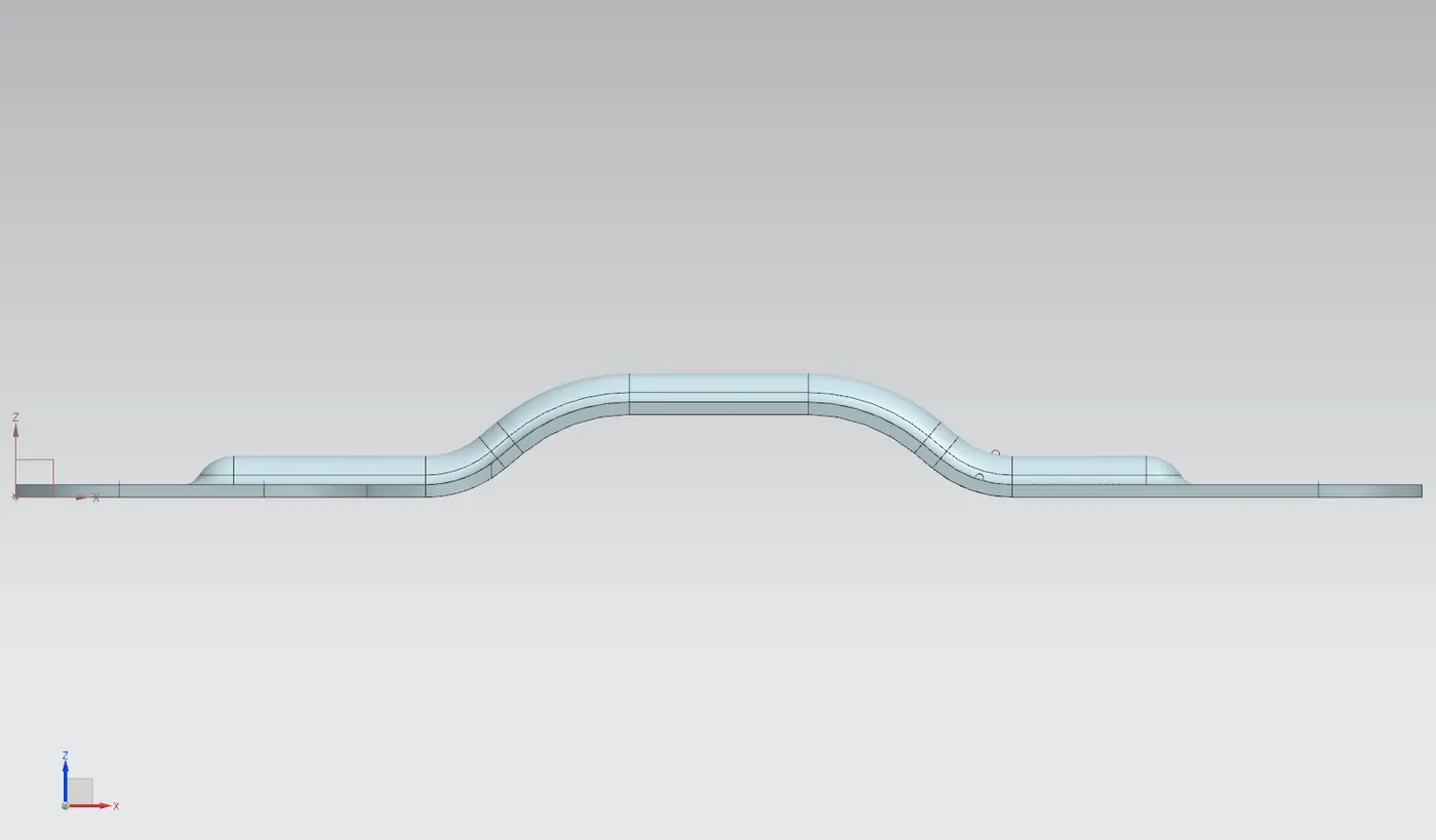
2. Front View
3. Left View
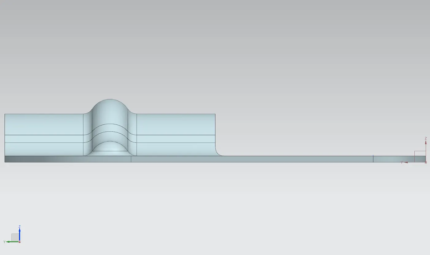
4. Right View
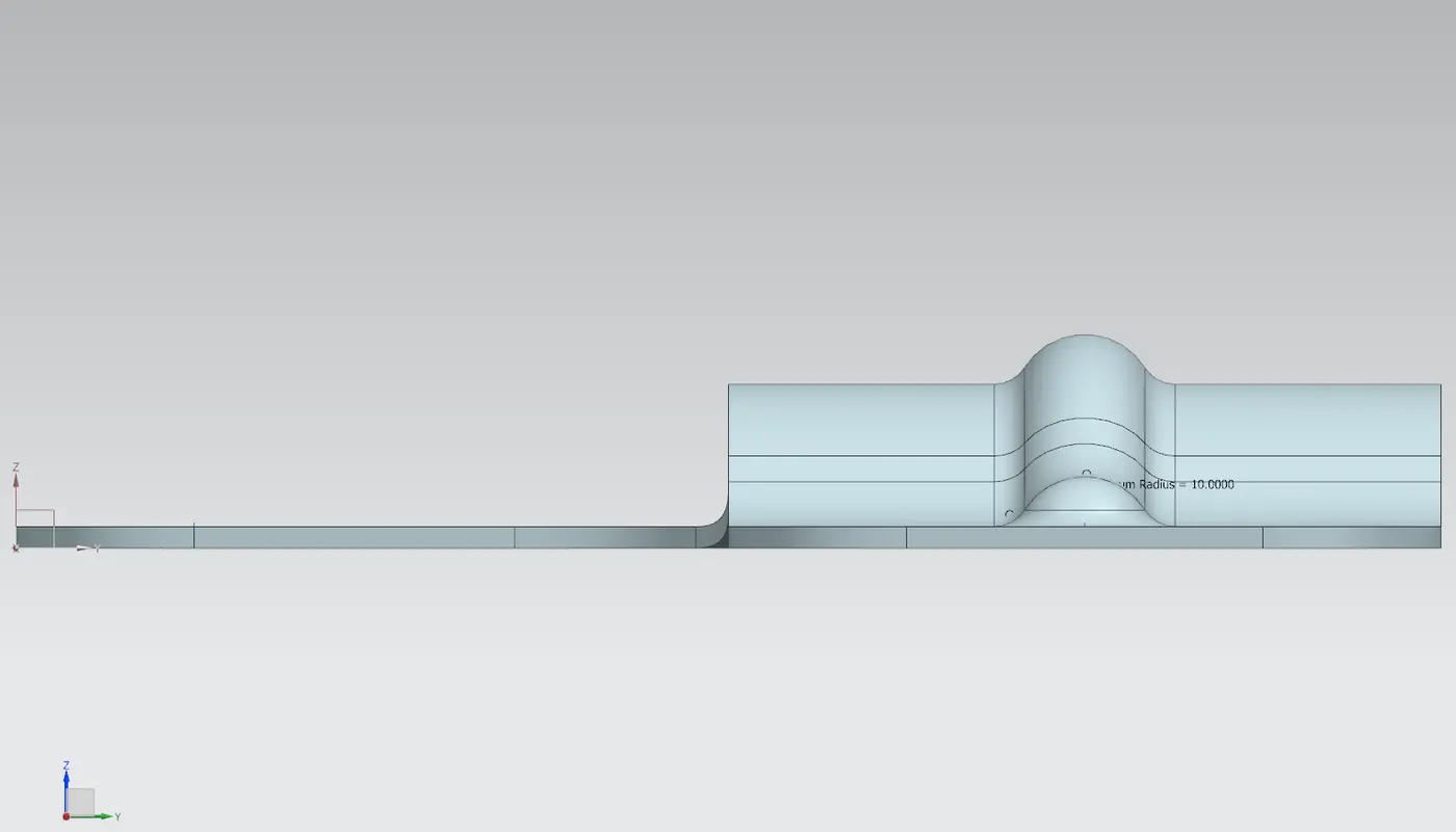
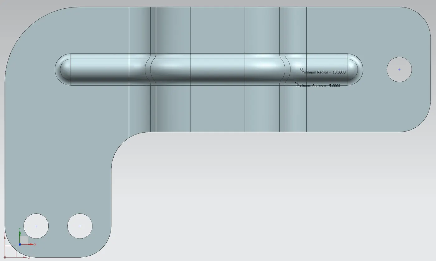
5. Top View