Advanced Sheet Metal Design Using NX Cad Challenge_1_Casing Design
Sheet Metal Design of Casing
Objective
This report contains a detailed explanation of Sheet Metal Design of a Casing. The main objective of this course module is to learn the basics of Sheet Metal Design and also exploring most of the tools that are used in Sheet Metal Design using Siemens NX.
Introduction
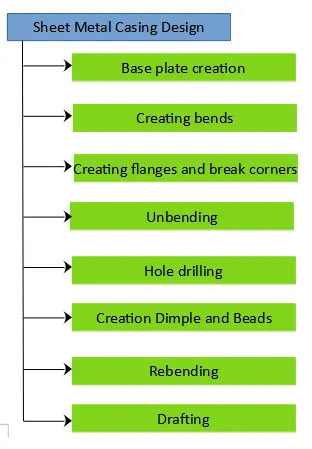
Sheet metal design is the process of making components from thin metal sheets by bending, cutting and fastening. Sheet metal design has varied application. The basics of sheet metal design are learnt and applied in creation of a Casing. The following steps were undertaking while designing the Sheet Metal Casing:
1. Creation of the base plate
2. Creation of bends, flanges and Break Corners
3. Unbend the component
4. Drilling holes
5. Sketch the profile for the creation of the Dimple on the center Face
6. Sketch and create Bead on the center face
7. Rebend the Component
8. Creation of the Draft
Design Methodology
Features
Sketches, Tab, Bend, Flange, Break Corner, Simple Screw Hole, Dimple, Bead, Unbend, Rebend, Flat Pattern and Drafting
Description
Create a sketch on the XY plane. A symmetric rectangle of dimension 60 mm x 50 mm is drawn and a tab of thickness 1 mm is generated. On the same plane create a small rectangle of dimension 5 mm x 40 mm. Normal cutout option is used to make a cut in the previously generated tab. Two lines are drawn on the upper face at a distance of 10 mm from either sides of the tab. The metal sheet is bent along these lines using bend feature. Create 4 flanges of 5 mm length on either sides of the component. Later using breaking corner option to fillet the sharp edges of the component of 1 mm. Now using unbend option, flatten the entire component to create sketch. Sketch 4 points on the bent flanges and create holes using Simple Screw Hole feature.
After the creation of the hole, another sketch of the required dimension is drawn on the XY plane along the surface of the component. Using Studio Spline option connect major point on the previously drawn sketches to create a continuous curve. Using Move command the curve is rotated to 45 degrees. This curve is used to create a dimple on the surface of the component with depth of 1 mm and rounding parameters to 1 mm.
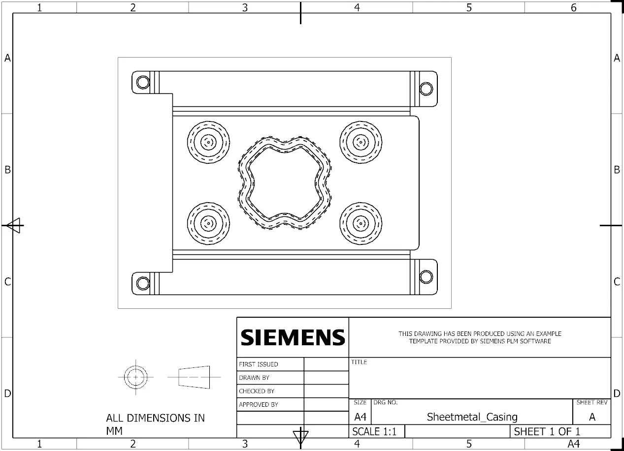
Again on the XY plane create a sketch of 4 circles around the previously created dimple using the specified dimensions, i.e., diameter of 5 mm and the circles are situated at 8 mm away from the bend and also from the rectangular cutout. Using the Bead feature and the sketch of the circle, beads are created on the surface of the component with depth of 1 mm, radius of 1 mm and rounding parameters of 1 mm. At last the faces are rebent using the Rebend option in the same order in which they were bent from the beginning. Finally a drat of the component with Flat Pattern view is created on an A4 sheet.
Views
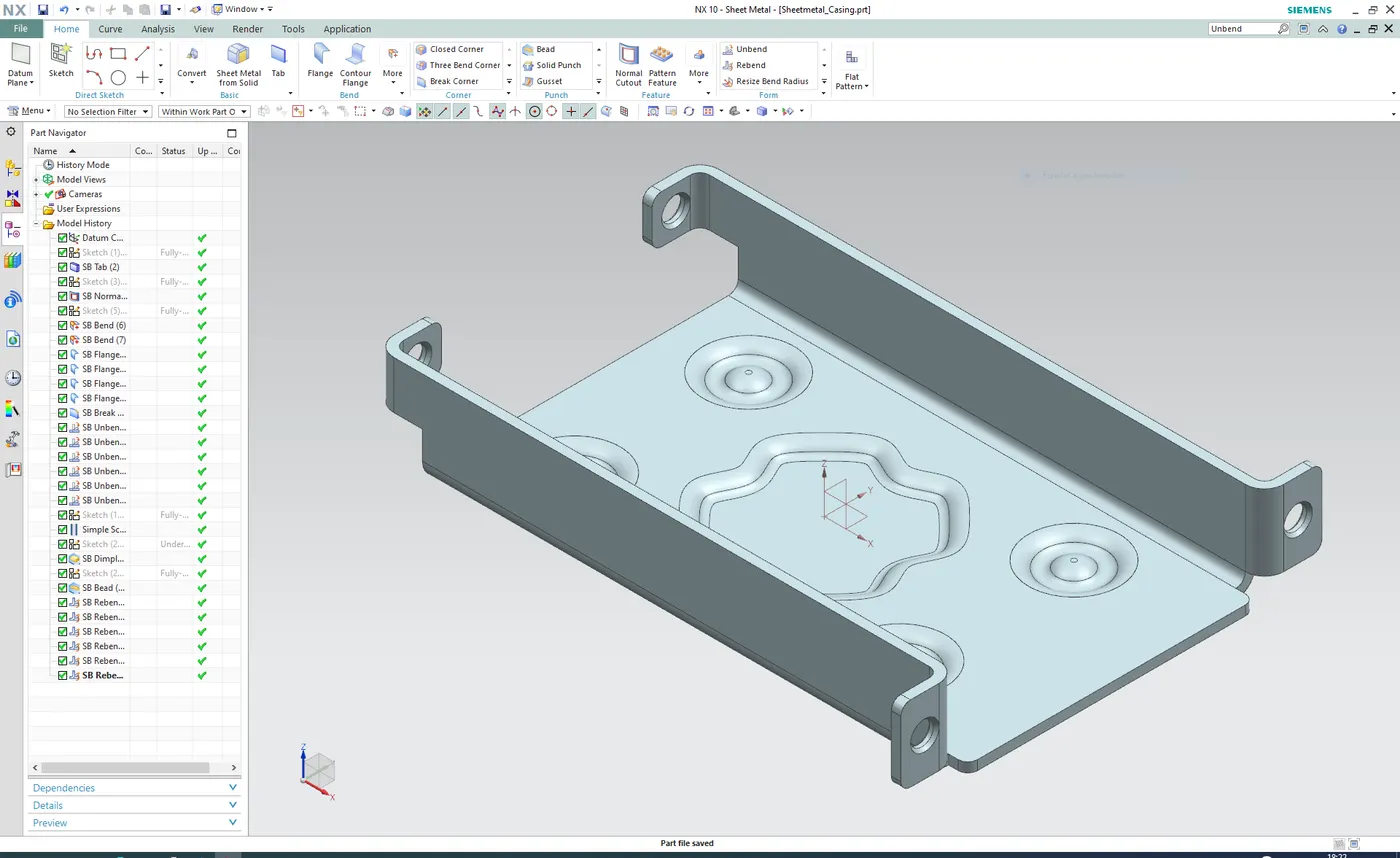
1. Isometric View
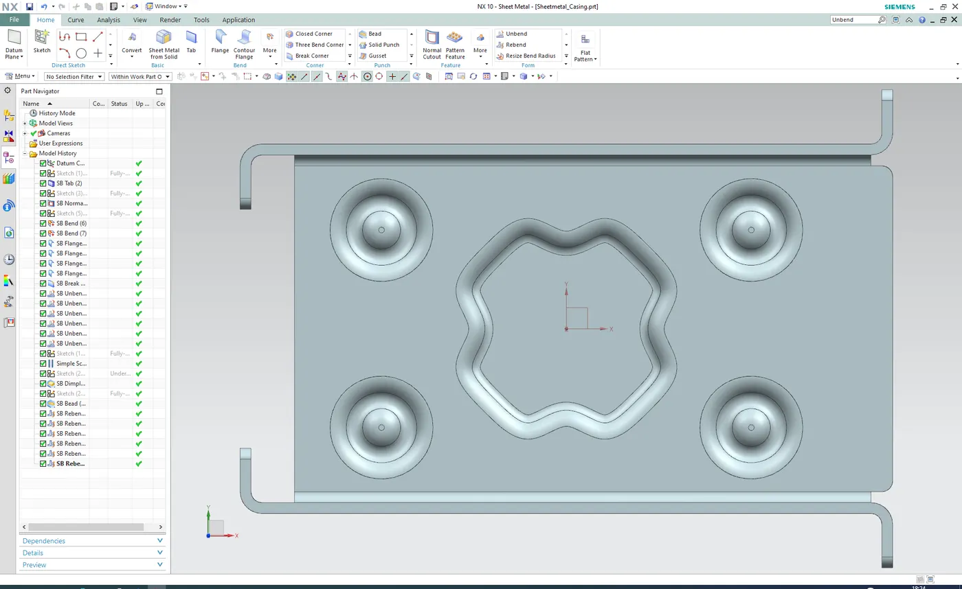
2. Top View
3. Left View
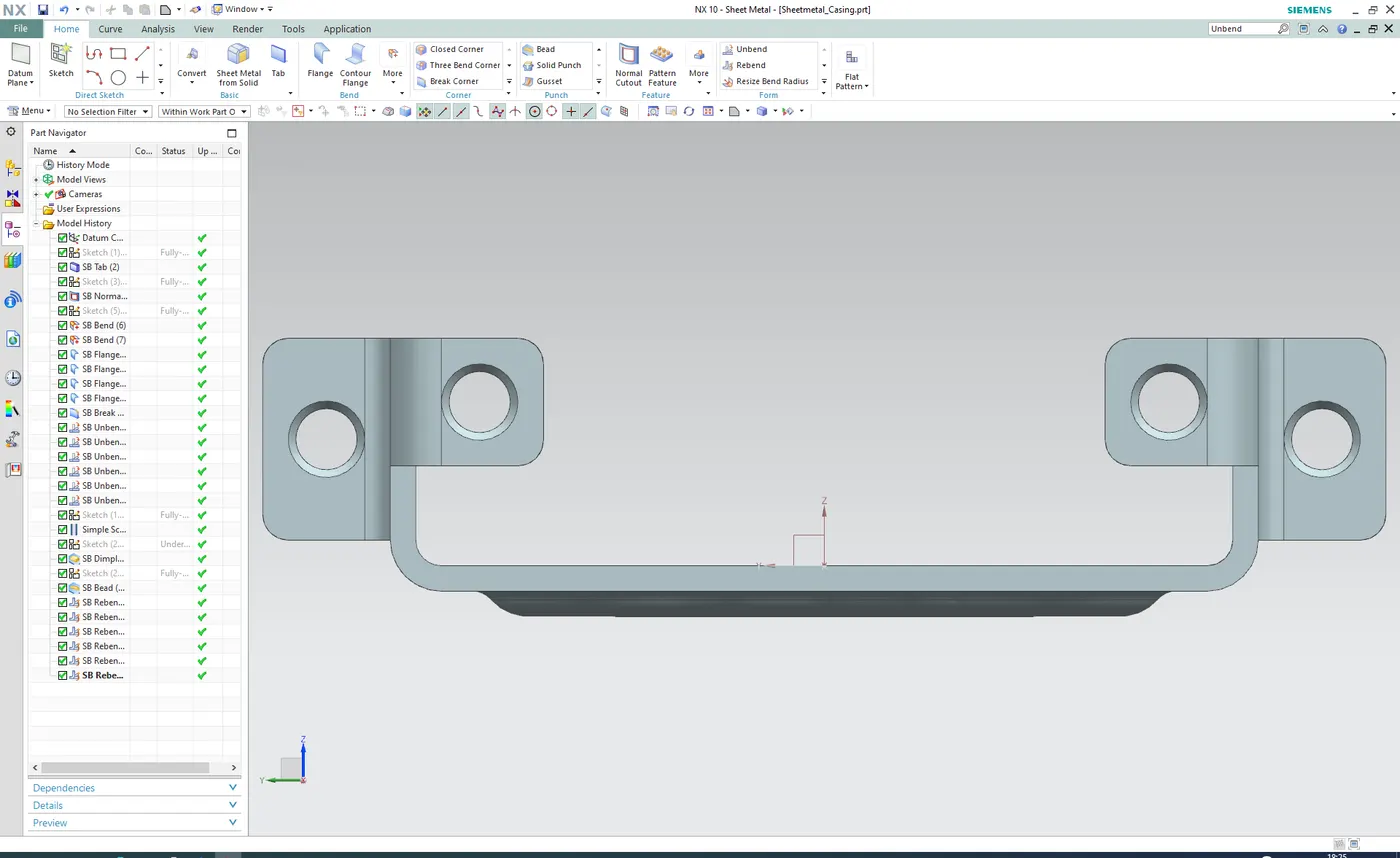
4. Front View
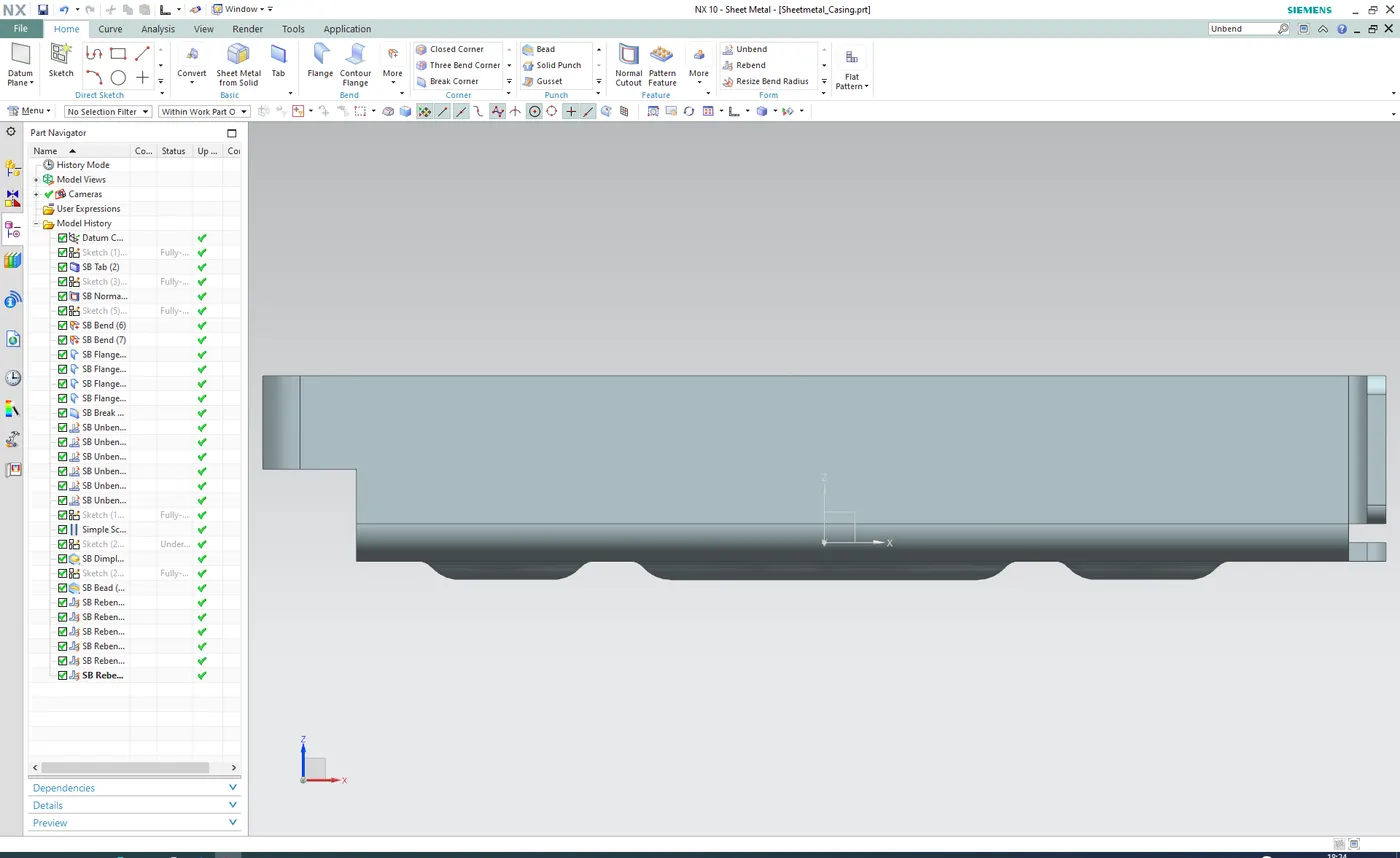
5. Drawing sheet