Advanced Sheet Metal Design Using NX Cad Challenge_6_Bracket
* Title : Report on Sheet Metal Component with good explanation on Sheet Metal modelling of Sheet Metal Bracket.
* Objective : To Write a detailed report on Sheet Metal Component with good explanation on Sheet Metal modelling tools applied throughout the modelling.And to attach the different views images of Sheet Metal Bracket.
* Introduction :
* Opening NX cad and starting with line sketch .
* Performing tab or contour flange .
* Performing of normal cutout with break corner and beads with unbend ,rebend.
* Design methodology :
| Opening NX CAD. |
| Performing of Sketch and Contour flange . |
| Perfroming of sketch for Normal cutout and performing of normal cutout . |
| Using Unbend and performing of break cornor. |
| Sketching For performance of beads . |
| Providing Holes and Final model |
* Description :
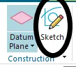
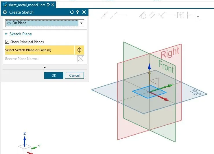
* Open the Nx cad and start with a plane the sketch .
* Sketch : This creates a line element for generating a geometry or a surface .
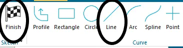
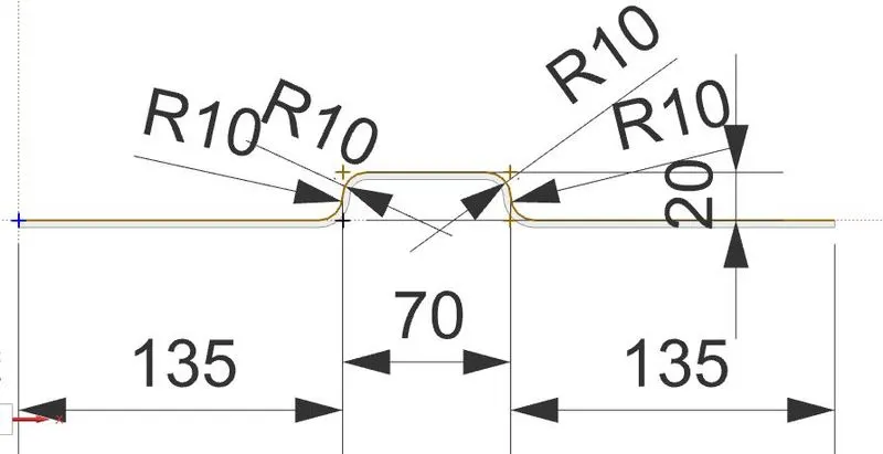
* Select line after selecting the plane and sketch for bracket ,click to finish as shown below .
* Model After performing sketch :
*Performing of Countour Flange :
* Contour Flange : The Process of creating base feature
by extruding sketch along a vector or adds material by sweeping a sketch along the edge.
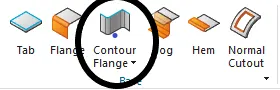
* From base tool bar ,select the contour flange and select the sketch.
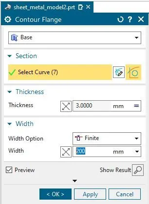
*Now given extrude width to 200mm and thickness as 3mm ,click ok as shown below .
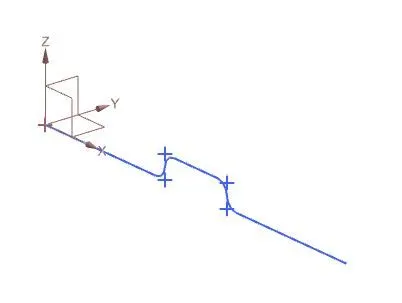
* Model Before performing countour Flange :
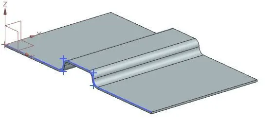
* Model After performing countour Flange :
* Performing of Normal cutout :
* Normal cutout : The process that cuts a material by projecting a sketch onto the model and then cutting perpendicular to the faces intersected by the projection .
* Before performing of Normalcut ,perform a sketch for normal cutout .
* select the plane and start sketching .
* From base tool bar select the sketch and sketch using line with parameters as shown below .
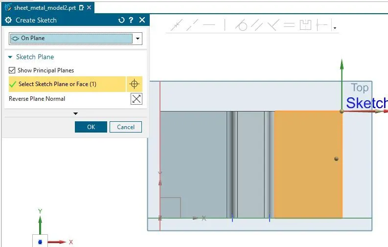
* Model Before sketching :
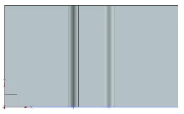
* Model After sketching :
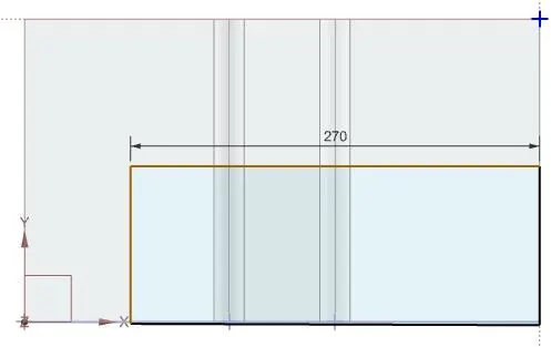
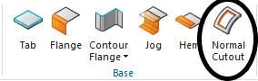
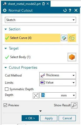
* Now for Perfroming normal cutout ,select normal cutout from base and select the sketch.
* Therefore givening the as 35 mm and click ok .
* Model before performing of normal cutout :
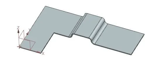
* Model After performing of normal cutout :
* Performing of Break Corner :
Break Corner : Here , the sharp surface are converted into rounds or a champers .
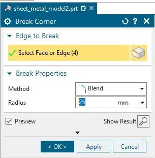
* From corner tool select the break corner .
* Select the sharpe edges and give the radius of 25mm and click ok as shown.

* Model before performing Break corner :
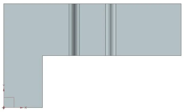
* Model After performing Break corner :
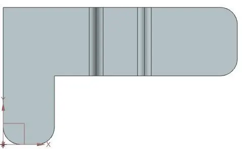
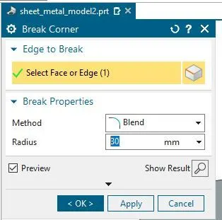
* Performing of break corner for 30 mm :
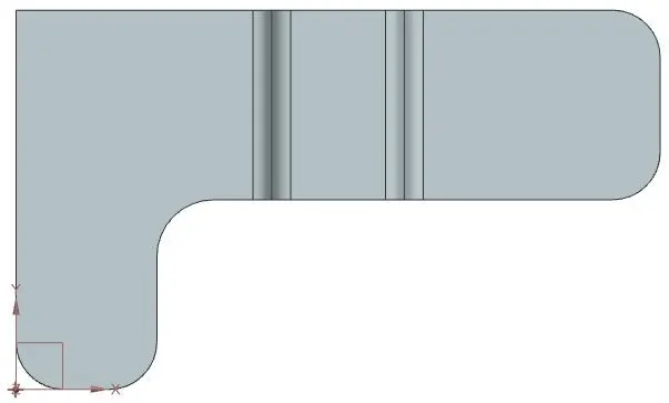
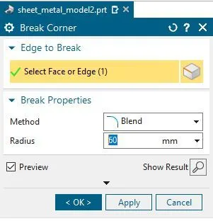
* Performing of break corner for 60 mm :
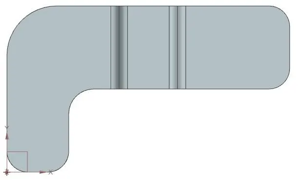
* Performing of unbend :
Unbend : The process of flatten the model with respect to selected surface .
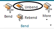
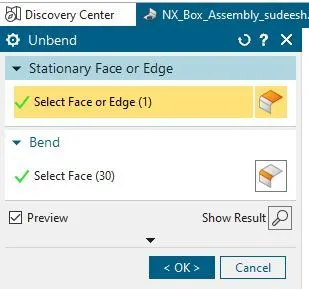
* From Bend tool select the unbend and select surface with respect to ,click ok as shown below .
* Model before Unbend :
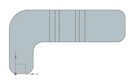
* Model After Unbend :
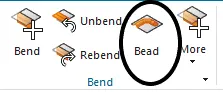
* Perfroming of Beads :
Beads : The Process That lifts a material along the contour of sketch that stimulates a stamping tool.
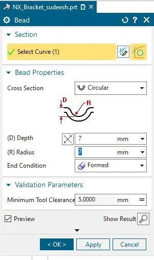
* Select beads from bend and sketch a line with required parameters .
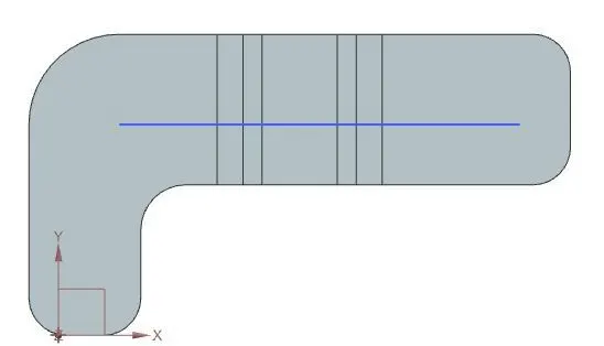
* The sketch must be drawn on the surface where the lifts has to be taken .
* Give the parameters as depth and radius as 7mm and click ok
* Model before beads and sketch performed :
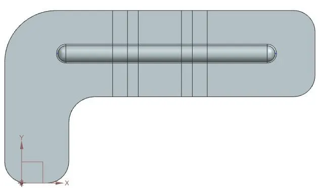
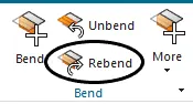
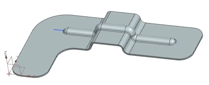
* Rebend : The process restores the unbend feature to its previous bent state, along with any features added after the unbend feature.
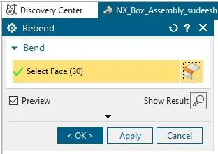
* From bend tool bar select rebend and drag the surface which to be in previous state .
* Click ok as shown below ;
* Model before performing rebend :
* Model before performing rebend :
* Performing of Holes :
* Holes : The process of extruding the surface with given depth .
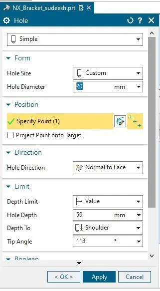
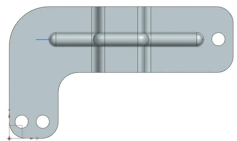
* From tool bar select the holes and specify the point with distance .
* Give the hole daimeter as 20mm as shown below ;
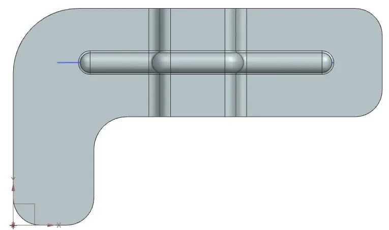
* Model before performing hole :
* Model After performing hole :
* Conclusion :
The given model can be generated contour flange ,Normalcutout,unbend and rebend for a bracket model .