Advanced Sheet Metal Design Using NX Cad Challenge_6_Bracket
Design of Bracket using NX-12
Objective:-
The main objective of the assignment is to learn to design the sheet metal component in the NX-12 software by using its various tools and features and drafting it onto the drawing sheet.
Introduction:-
Design of bracket using the NX-12 software by using various tools and features of the software like counter flange, normal cutout, bend, rebend bead, holes, flat pattern, etc.
The design of the bracket is done in the sheet metal workbench as the component is made to be manufactured in the sheet metal process like stamping, bending, punching, cutting, etc.
Methodology:-
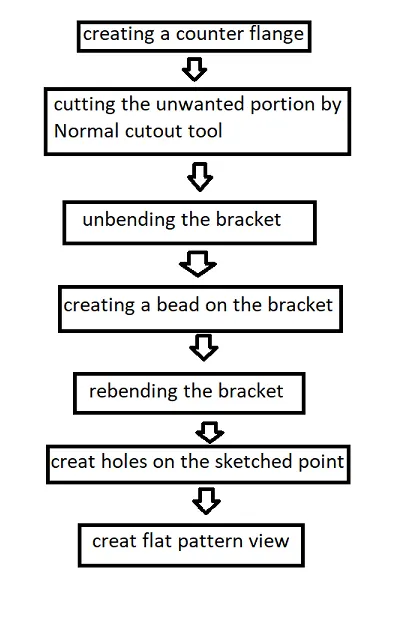
The methodology for designing the bracket is as shown below on the flow chart-
Description:-
All the features and tools used in the design of the bracket are as follows-
Contour Flange-
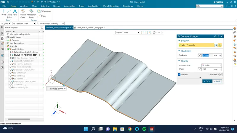
Countour flange is used by selecting the sketch drawn to create the bracket body.
Normal cutout-
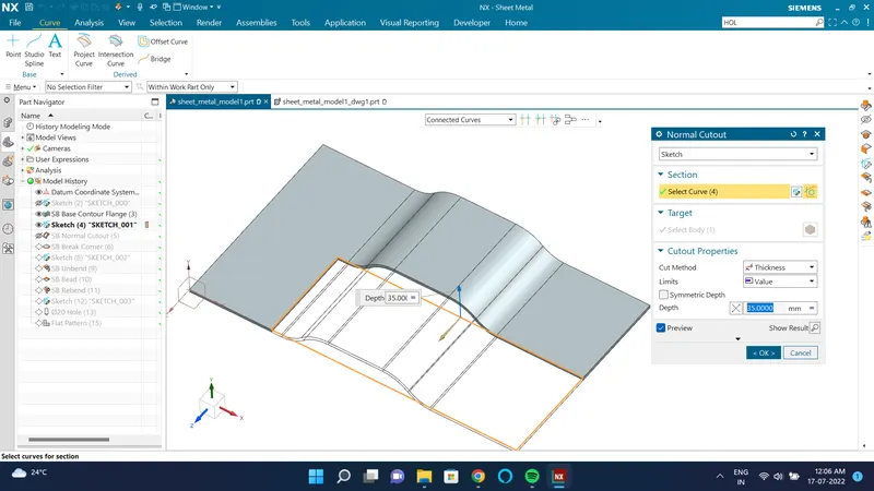
The normal cutout is used by selecting the sketch to cut the unwanted portion and get the desired body.
Break corner-
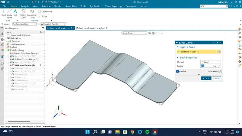
The break corner tool is used to blend the edges and give some relief to the corner to avoid stress concentration.
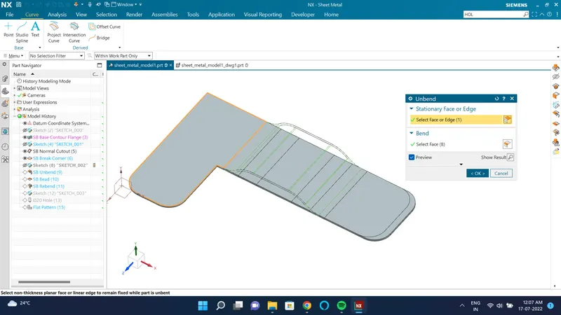
Unbend-
Unbend feature is used to unbend the sheet metal part created.
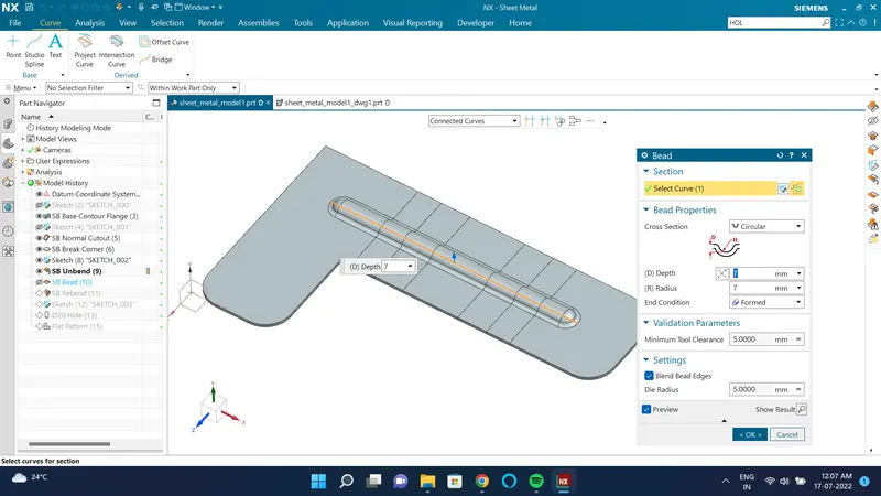
Bead-
After the body is unbent the bead is given by selecting the sketch.
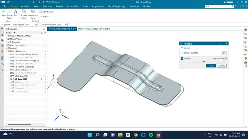
Rebend-
The body is rebent to its original position by using the feature rebend.
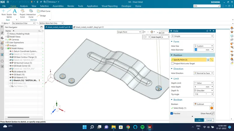
Hole-
Hole tool is used to create holes on the bracket by sketching the points on the bracket.
Flat pattern-
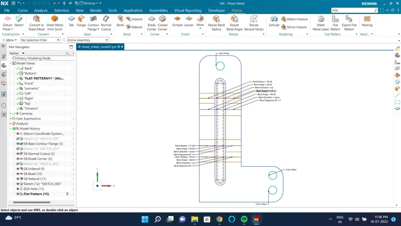
A flat pattern view is achieved by using the flat pattern feature.
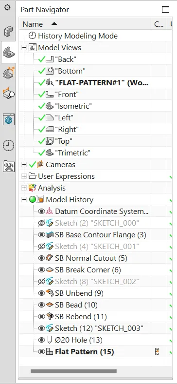
Tree of the bracket-
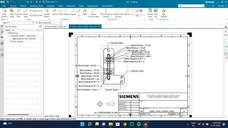
Drawing sheet of the bracket-
Views of the bracket:-
Front view-
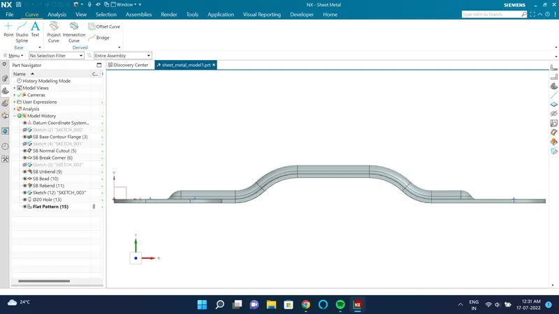
Top view-
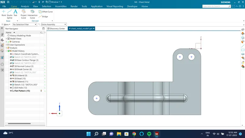
Side view-
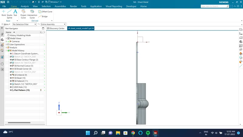
Isometric view-
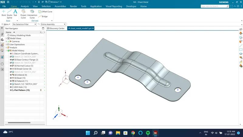
Conclusion:-
In designing the bracket using the NX-12 software, we learned different types of tools and features like contour flange, normal cutout, bead, hole, etc.