Advanced Sheet Metal Design Using NX Cad Challenge_6_Bracket
BRACKET
Objective: To design and analysis the given sheet metal component "Bracket" in Siemens NX CAD software.
Introduction:
- The given sheet metal component is for practice and to get familiar with the commands in sheet metal design.
Design methodology:
1. Sketching the shape
2. Construction of base feature
3. Adding the features
4. Unbend and adding cutouts
5. Creating flat pattern
Tools/Features used:
1. Sketch: It creates a sketch in the current application. Use the direct sketch tools to add curves, dimensions, constraints, etc.
2. Contour Flange: It creates a base feature by extruding a sketch along a vector or adds the material by sweeping a sketch along an edge or chain of edges.
3. Normal Cutout: This feature cuts the material by projecting a sketch onto the model and then cutting perpendicular to the faces intersected by the projection.
4. Break Corner: This feature rounds or chamfers a sharp corner of a tab or flange.
5. Unbend: This feature flattens a unbend and the material adjacent to the bend.
6. Bead: This feature lifts the material along the contour of a sketch that simulates the stamping tool.
7. Rebend: This tool restores an unbend feature to its previous bent state, along with any features added after the unbend feature.
8. Hole: This feature adds a hole to one or more solid bodies in a part or assembly with options for the counterbored, countersunk and threaded.
9. Flat Pattern: This tool creates a flat pattern feature from the formed sheet metal part.
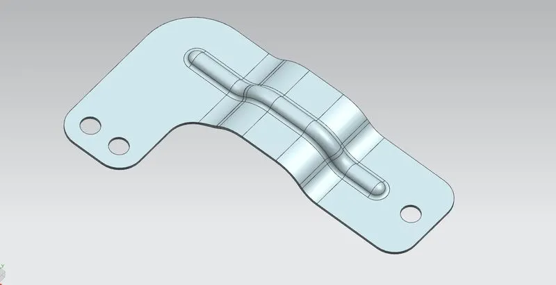
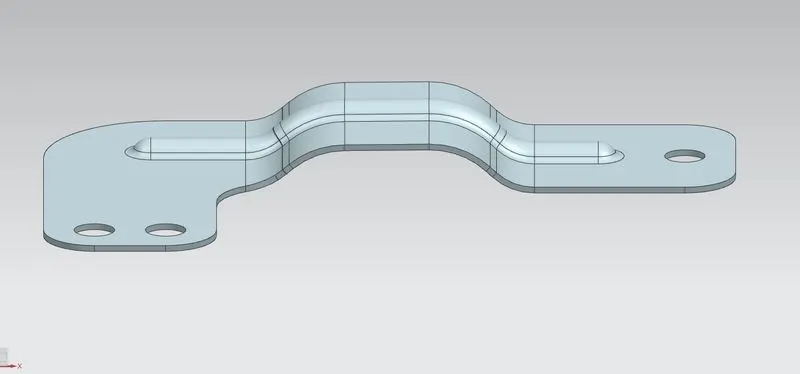
Trimetric view Front view
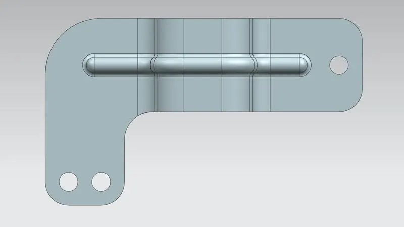
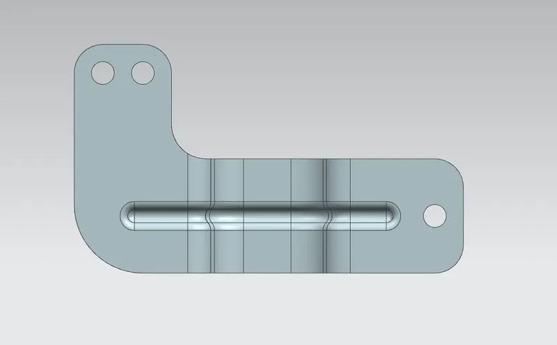
Top view Bottom view
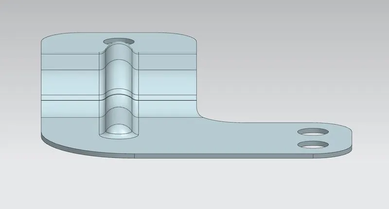
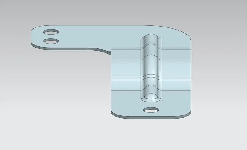
Left view Right view
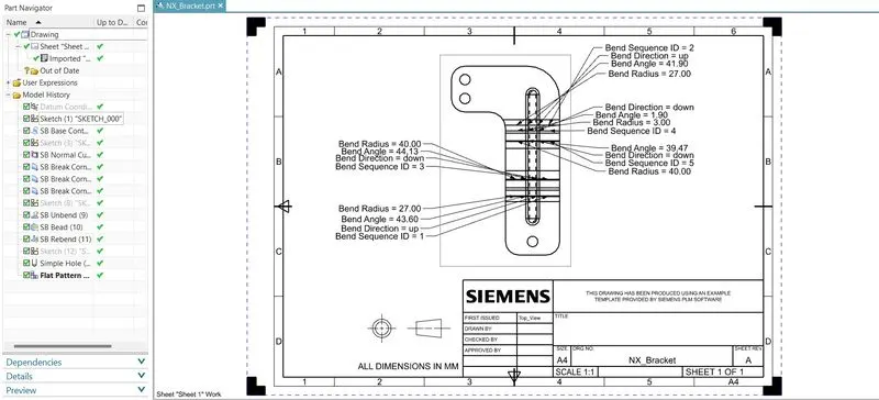
Draft Sheet
Conclusion: So the given sheet metal component "Bracket" has been designed with the given dimensions using the commands/tools above in Siemens NX CAD software and the final results are shown above.