Advanced Sheet Metal Design Using NX Cad Challenge_6_Bracket
Bracket Design
Objective
To design the Bracket using the CAD software (Siemens NX - Sheetmetal Application)
Introduction
Sheetmetal application provides an environment for the design of sheetmetal parts used in machinery, automotive and various industries
Design Approach
The design workflow of the Bracket Design is given below
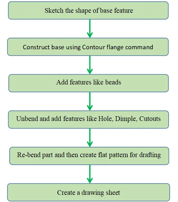
Description
The following features were used in the Bracket Design
- Sketch
2D sketch of the part is created in the sheetmetal application
- Contour Flange
This command is used for creating a flange by extruding a sketch along a vector, or by sweeping a sketch along an edge or a chain of edges
- Normal cut-out
Cut-outs in sheetmetal is made with this command which cuts material by projecting a sketch onto the model and then cutting perpendicular to the faces intersected by the projection
- Break corner
The sharp corners are made round or chamfer with this command
- Unbend
This command is used for flattening a bend and the material adjacent to the bend
- Bead
This command is used for lifting material along the contour of a sketch that simulates a stamping tool
- Re-bend
This command is used for restoring an unbend feature to its previous bend state, along with any features added after the unbend feature
- Hole
This command is used for adding general type of holes in the part
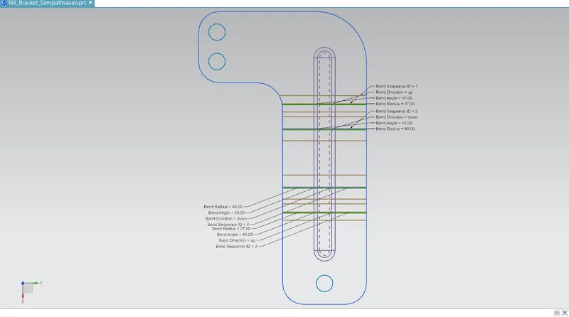
- Flat pattern
This command is used for creating a flat pattern feature from the formed sheetmetal part
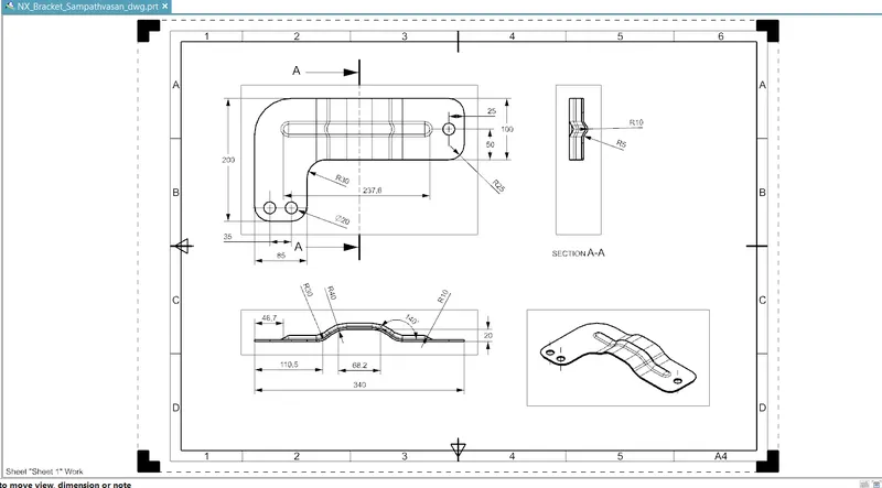
- Base view
This command is used for creating a model based view (front/top/isometric/flat pattern) on the drawing sheet which is available in the Drafting application
Views of Bracket Design in NX Sheetmetal Application
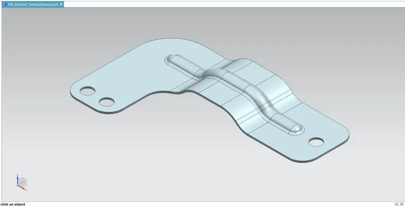
Isometric view
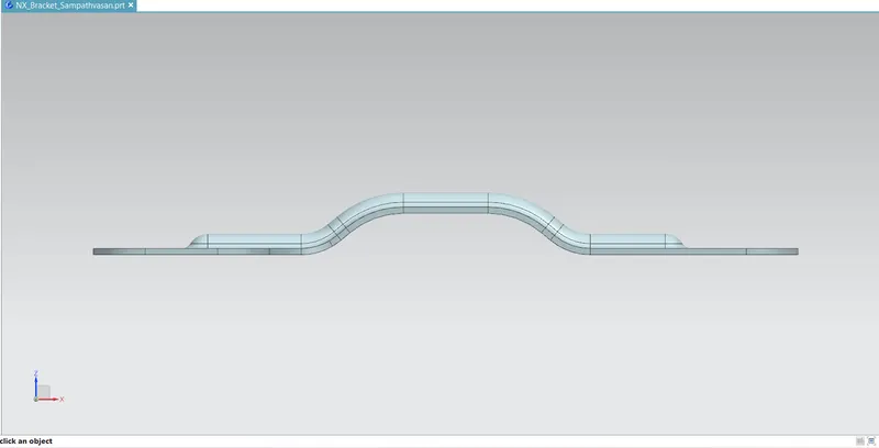
Front view
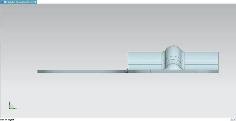
Right side view
Top view
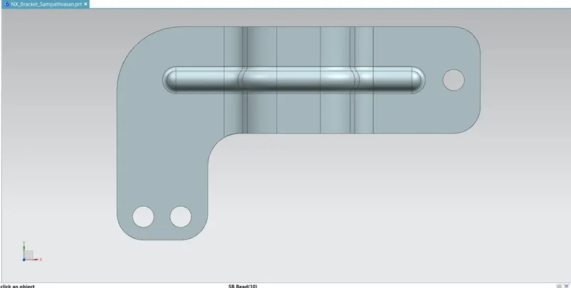
Flat pattern
Drawing Sheet
Conclusion
In this project, Bracket designed successfully in the sheetmetal workbench of Siemens NX and drawing sheet is also prepared and attached.