Advanced Sheet Metal Design Using NX Cad Challenge_6_Bracket
DESIGN OF BRACKET USING NX CAD
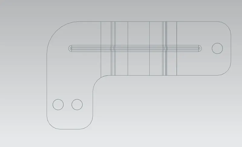
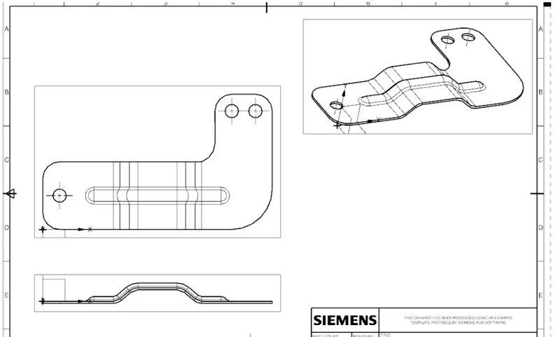
Objective: To model an L-shaped bracket with given 2-D input.
Introduction:
Sheet metal brackets have a variety of applications in the automobile industry. Depending on the application and working conditions different materials can be used to create brackets. Such as Titanium, Aluminum, plastic material, Ceramic, etc. In this project we are going to model a simple L-shaped a bracket using the given 2-D data.
Design Methodology:
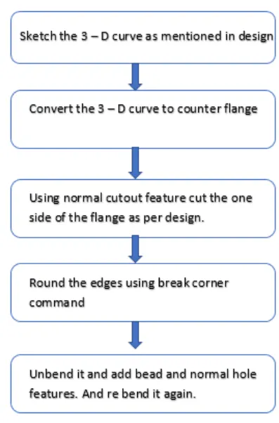
Description:
Sketch:
Sketch an autline of contour flange feature with dimentions form a front view.
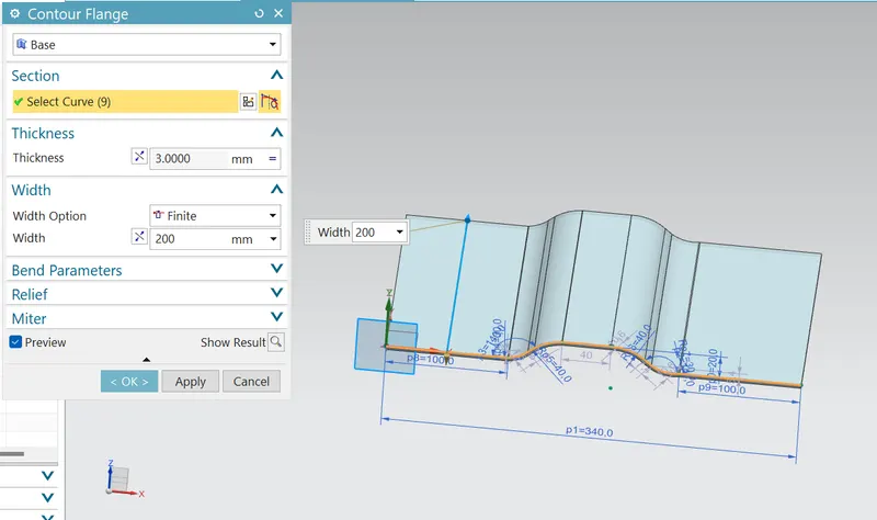
Contour Flange:
It wil extrude the outline of the sketch along a vector, the thickness of the sheet metal is initially provided.
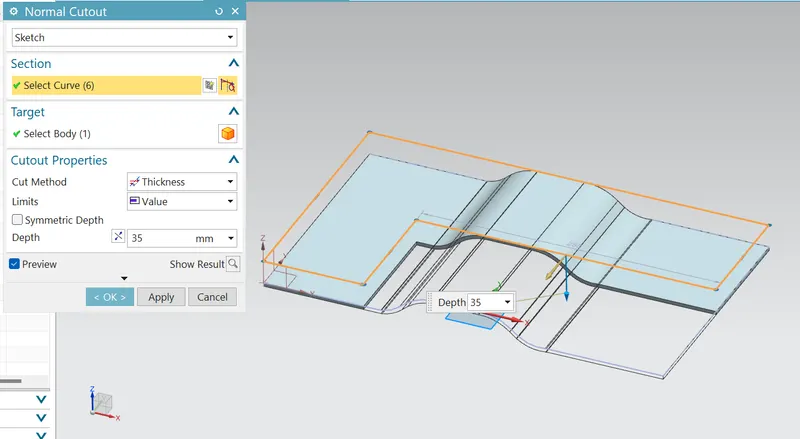
Normal Cutout:
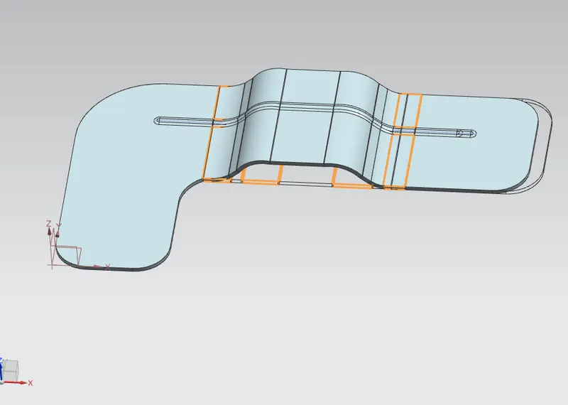
Normal cutout is used to remove the excess material from the part and provide the required geometric part.
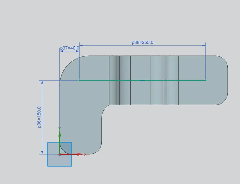
Break cornor:
Break cornor is used to provide a fillet type faster to the sharp cornors of the sheet metal. It is used to provide safety as well as to relieve stress concentration.
Bead:
Bead feature will provide stiffeness to the bracket. The height of the feature is kept according to DFM guidelines.
Hole:
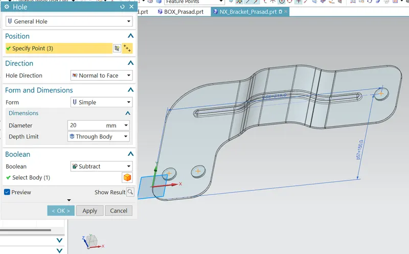
Hole command is used to provide mounting holes for the bracket all the holes have a size of M18 with a fit of H13. The distance from the edges is also according to DFM standards.
Conclusion:
- The project helps in understanding the workflow process used in the industry for a sheet metal bracket part.
- Knowledge of various DFM guidelines for various fearures is acquired during the project.
Google link: https://drive.google.com/file/d/15ZNidW5QusR5PE2eOOb4Zaj9x_1zcGoT/view?usp=sharing