Advanced Sheet Metal Design Using NX Cad Challenge_6_Bracket
BRACKET
OBJECTIVE
To observe the model and design the sheet metal by using given dimensional parameters and instructions in Siemens NX software.
INTRODUCTION
In this project we are going to learn about the different manufacturing processes that can be performed on a sheet metal. There is a factor known as the "K" factor which aids us in giving appropriate bend radius to the available sheet metal thickness. The K-factor comes from the ratio of the neutral radius divided by the thickness of the material on prepared charts and has a value between 0.3 and 0.5.
Sheet metal is metal formed by an industrial process into thin, flat pieces. Sheet metal is one of the fundamental forms used in metalworking, and it can be cut and bent into a variety of shapes. Countless everyday objects are fabricated from sheet metal. Thicknesses can vary significantly; extremely thin sheets are considered foil or leaf, and pieces thicker than 6 mm (0.25 in) are considered plate steel or "structural steel".
DESIGN METHODOLOGY
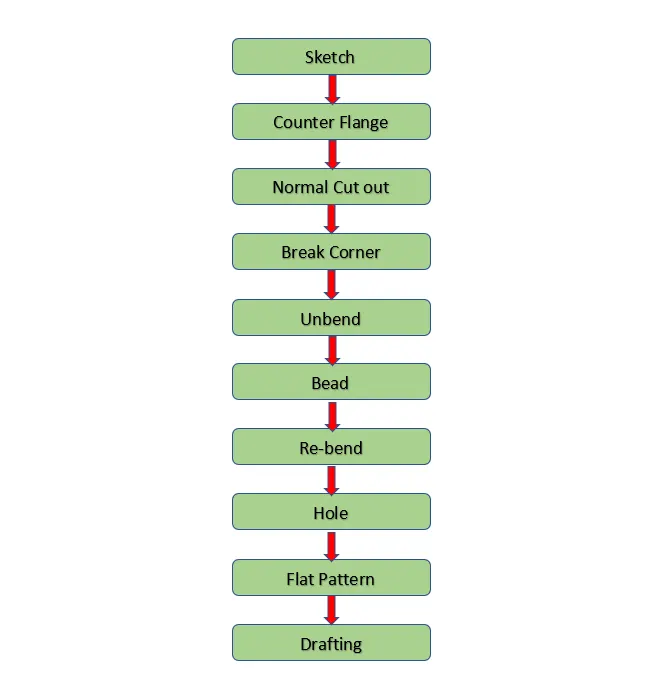
The sheet metal preferences are set before the creation of a 3D element. The most important method we follow for the design of any sheet metal component is that, if we want to create beads, we need to first unbent the whole sheet metal model and make it a flat sheet and then do the required features and after all features are created the model is rebented to get its final design. This is done for ease of designing and to get a properly positioned features.
DESCRIPTION
- Sketch
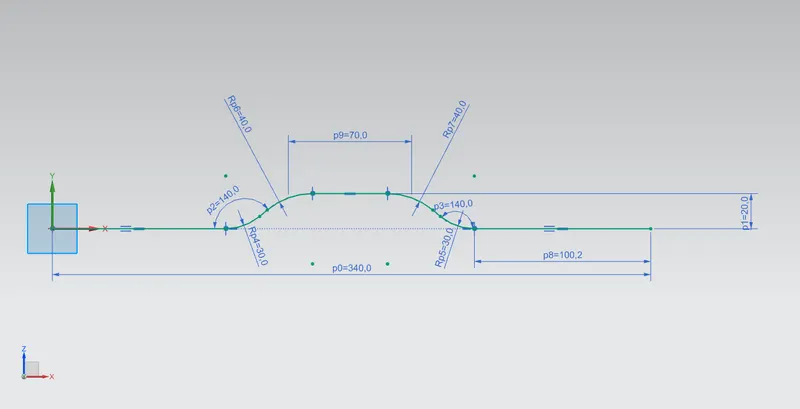
Making a 2D drawing is created using line, curve commands and appropriate dimenssions are given as per the guidelines.
- Counter Flange
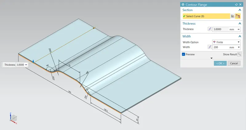
It is created by extending the sketch on its respective axis with thickness as required from the base. Here the thickness given is 3 mm and width is 200 mm.
- Normal Cutout
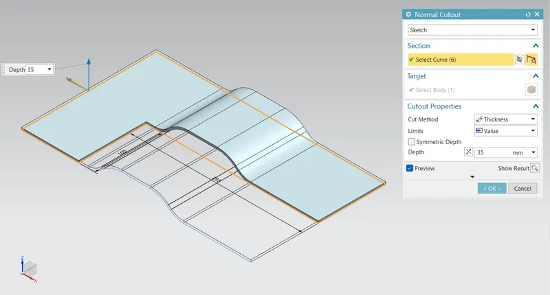
It extracts material volume from sheet metal by using sheet metal production principles. Cutting faces will be perpendicular to the sheet metal surface.
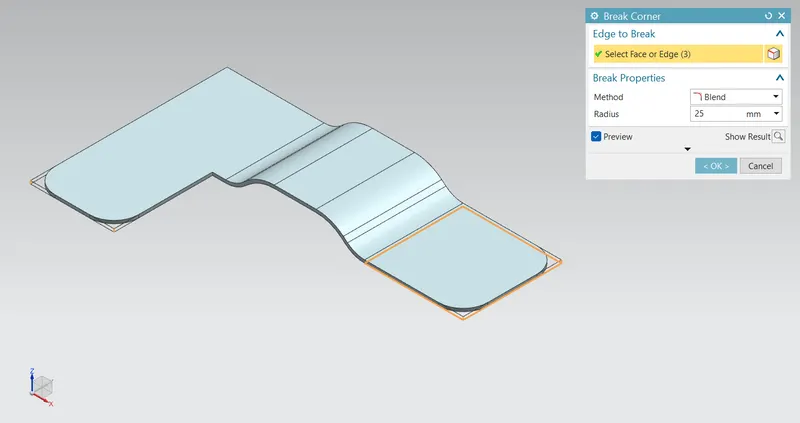
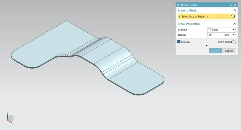
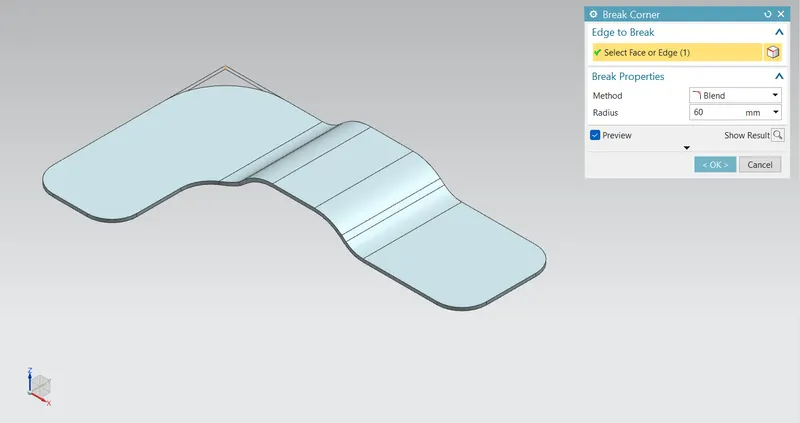
- Break Corner
It is used to round the sharp edges with user specific radius. The input parameters are the faces which connects the edges.
- Unbend
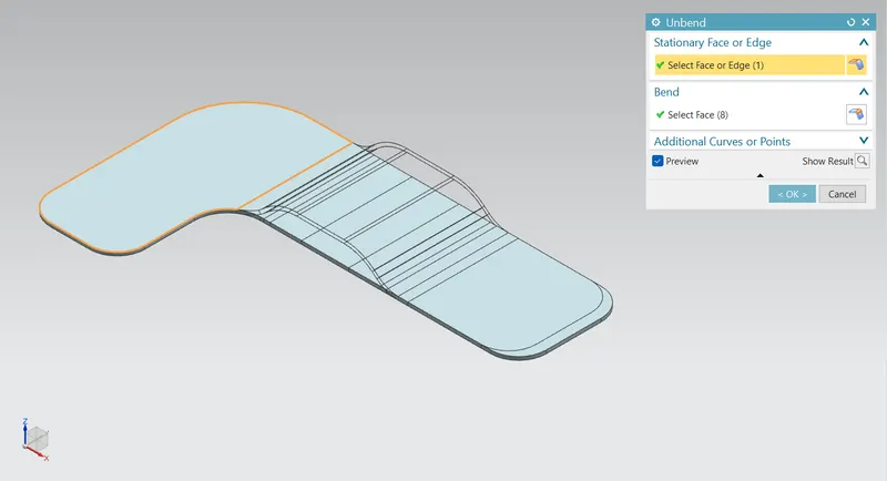
One or more curved surface such as bends or curved walls to a flat configuration in a sheet metal part. For performing a unbent feature, it must define a fixed planar face or edge. We can select the curved surface of the bend as the input parameter.
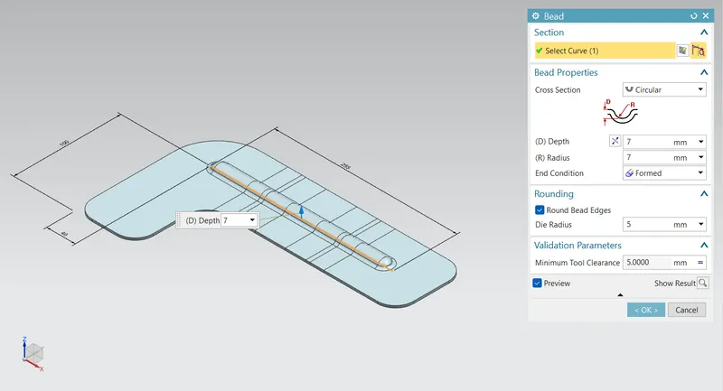
- Bead
Beads are the features added in sheet metal components in order to increase the stiffness of thee component. Beads require a sketch in order to apply the feature. It can be either an open or closed profile. For this casing design project, one point is sketched on the flat surface and bead is created with the help of that sketch.
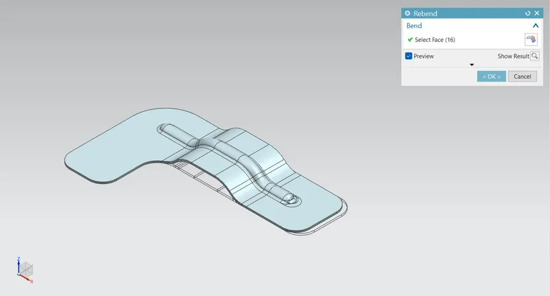
- Rebend
This command is used to rebend the unbent sheet metal along with the features applied sfter the unbent. After addition sketches and features the sheet metal is to be rebented to its required shape. This operation is done by box selecting all the features and clicking the rebend command.
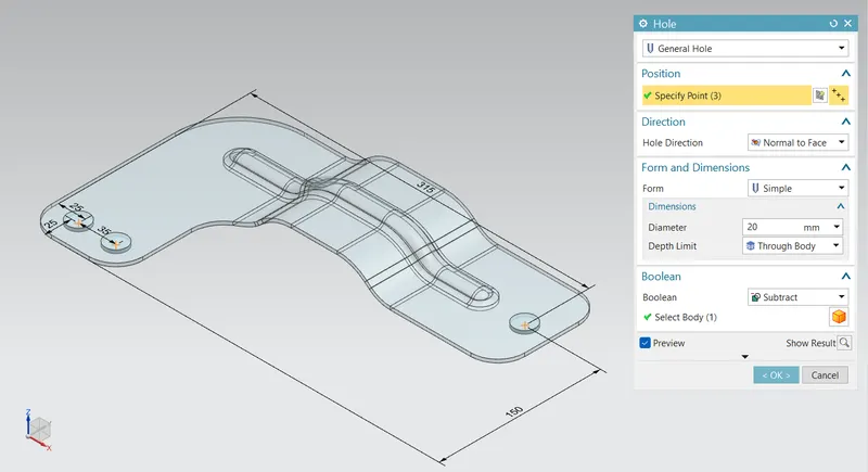
- Hole
General holes are created with the sketched points with a diameter of 20 mm. This tool created a counter bored, counter sink and several hole options.
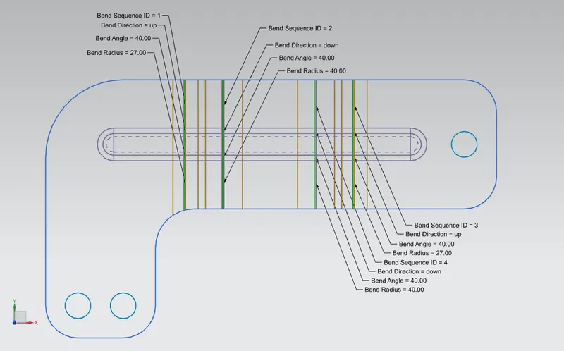
- Flat Pattern
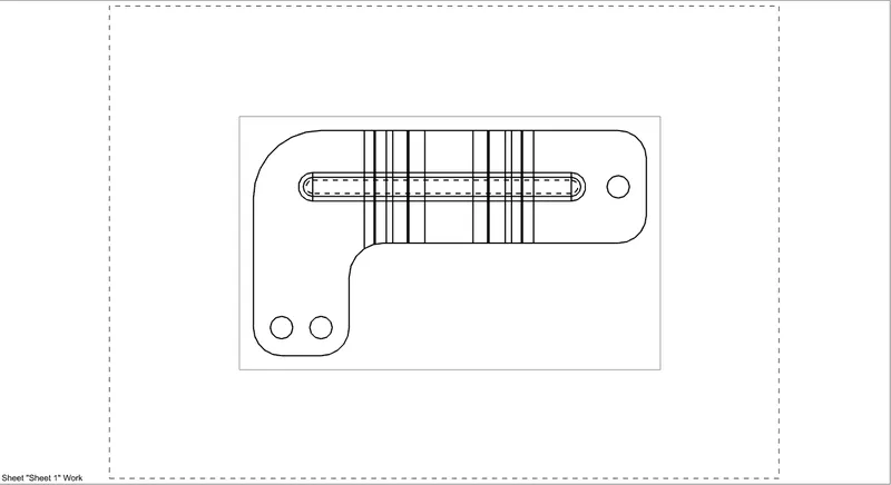
Flat pattern is the representation of the entire sheet metal component in the 2D form with all the bends, cutouts, holes and additional features in the form of lines or edges. The flat pattern ensures the ability to cut the sheet metal out of the raw sheet metal plate. It removes the possibility errors such as interference or collision within the same component.
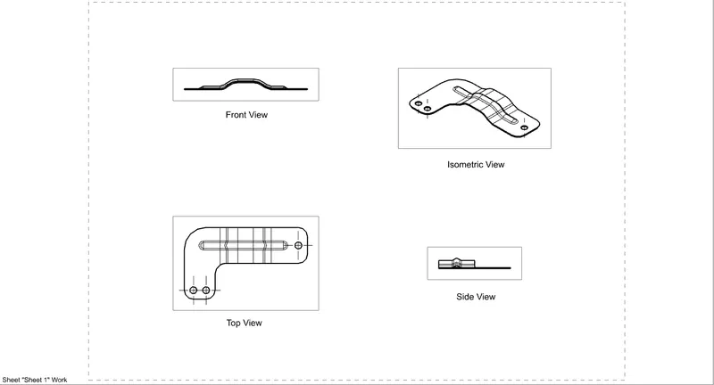
STANDARD VIEWS
- Front View
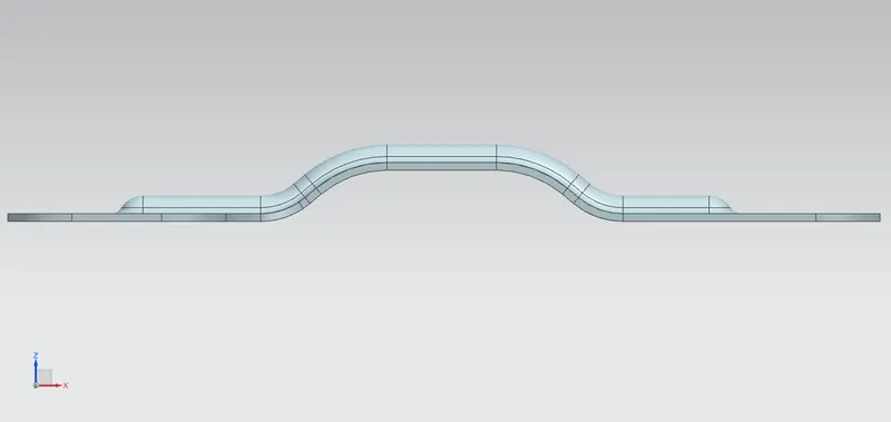
- Side View (Left)
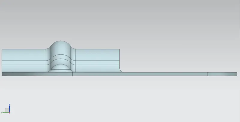
- Top View
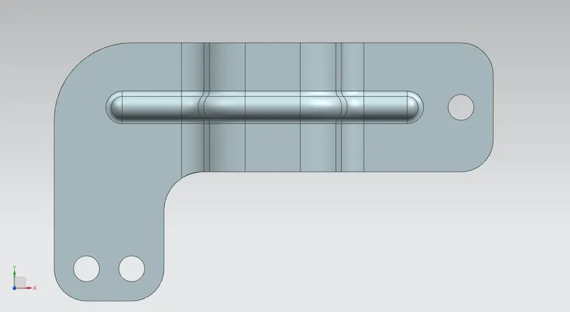
- Isometric View
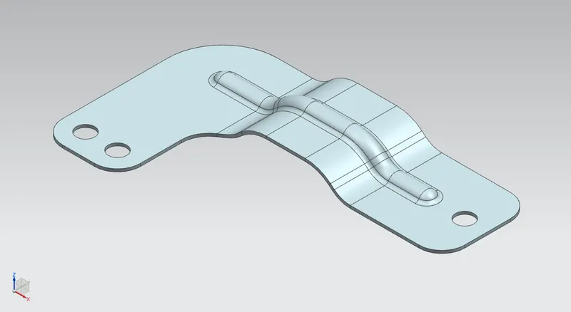
DRAWING SHEET IMAGES
Drafting application is used to get the 2D drawing sheet images. The size of the sheet is A4 and and the scale is 2:1
- Flat Pattern
- Standard Views
CONCLUSION
By using the proper design methodology and tools the sheet metal bracket design has been compleated using the Siemens NX software.