Advanced Sheet Metal Design Using NX Cad Challenge_6_Bracket
BRACKET
OBJECTIVE:
- To observe the model and design the sheet metal by using given dimensions and instructions
INTRODUCTION:
- NX is widely used Computer Aided Designing software for multi purposes like designing, engineering and manufacturing.
- It is used in various fields for different works. Using different features and methods we have designed here.
DESIGN METHODOLOGY:
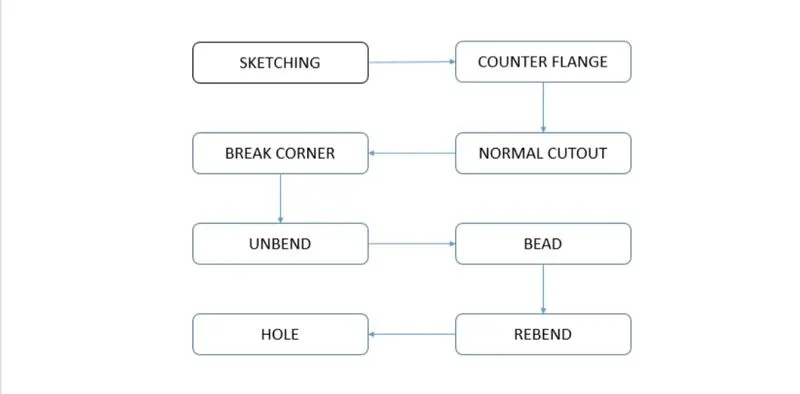
DESCRIPTIONS:
Sketching
- Making a 2d drawing such as curves, arcs, circles, points, rectangles and many options to create a drawing or to create features for upcoming designing.
Counter flange
- It is created by extending the sketch on its respective axis with thickness as required from the base.
Normal cutout
- It is used to create a cut portion or a gap on the sketch where there is a requirement.
Break corner
- This feature is for making the corner blend with some self dimensioned radius in order to make the corner smooth.
Unbend
- It is to flatten the bend sheet metal to form a flat sheet.
- It helps in making extra features like bead, normal cutout on the sheet metal after bending.
Bead
- This is to create a contour shaped accordingly to their sketch in the required direction with required punch/die radius,
Rebend
- It is to make flat surface that is bend previously to do some extra features like holes,bead back to its original form.
Hole
- It is to create a hole on sketch, or to create a counter bored, counter sink and several hole options to do.
MODEL VIEWS :
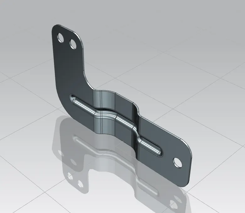
ISOMETRIC VIEW:
BACK VIEW :
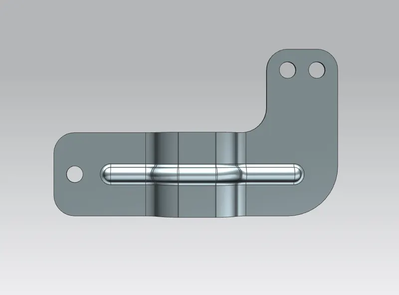
BOTTOM VIEW :
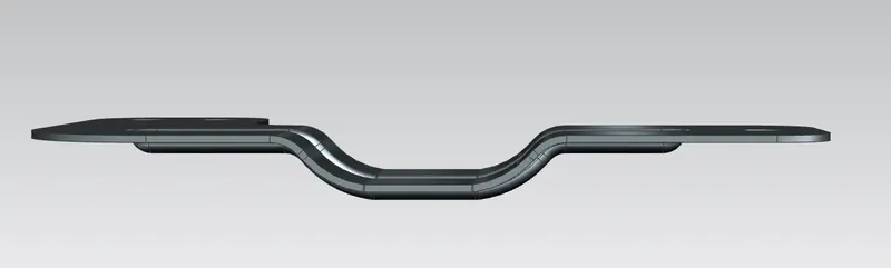
SIDE VIEW :
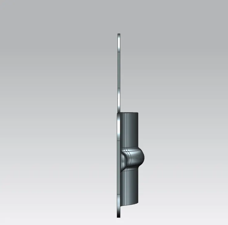
FRONT VIEW:
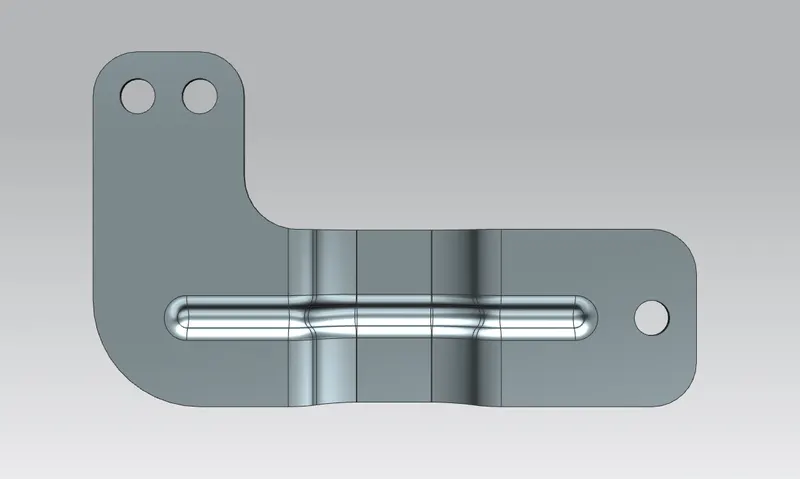
TOP VIEW:
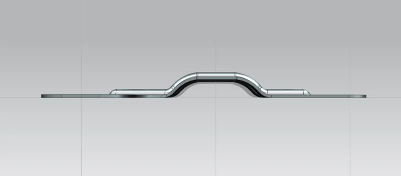
FUTURE TREE :
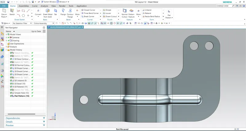
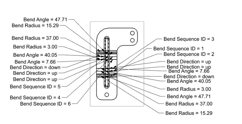
FLAT PATTERN :
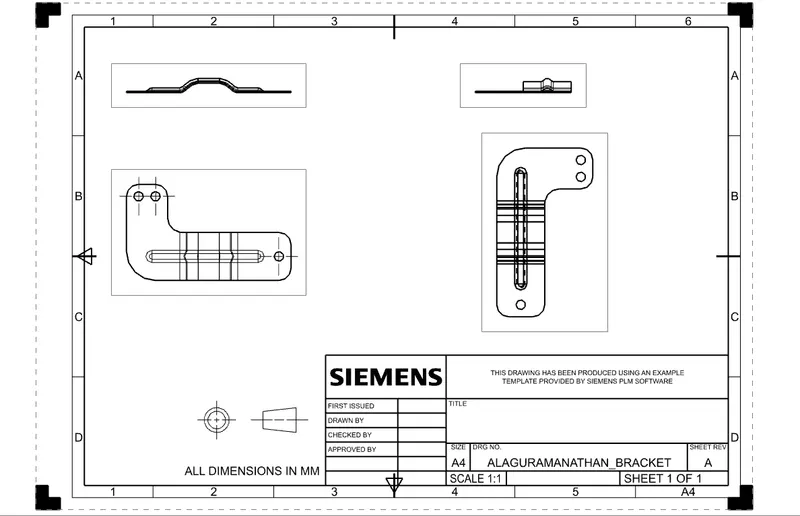
DRAFTING
MODEL FILE LINK :
https://drive.google.com/drive/folders/1adKgcceWhYuOe1Lwy8nmM8LdMetrFl18?usp=sharing
CONCLUSION:
- The model has been designed and dimensioned as given in the instructions with proper constraints.