Advanced Sheet Metal Design Using NX Cad Challenge_6_Bracket
PROJECT TITTLE: DESIGNING A BRACKET IN SHEET METAL
OBJECTIVE:
- To design a bracket in sheet metal from a given 2 dimesional diagram. by using NX_cadd_seimens
INTODUCTION
- As we know reading and understanding a drawing is very much important for design engineers. so here we are going to design a bracket from a 2 dimensional diagram by workinng NX_cad _seimens software. these brackets are pretty much use full for almost everywhere like tv,antenna,projector mountings and so on.
DESIGN METHODOLOGY
- the part that we are working on which is a single part not an assembly. while designing a sheet metal part make sure that we are designing for a manufacturing{DFM}.
- the designed part can be manufactured by variety of methods mostly used methods are
- stamping
- punching
- shearing
- welding
- cutting and etc.
for manufacturing we have to considered the sheet metal parameters to get a synchronized part.
DESIGN PROCESS FLOW CHART
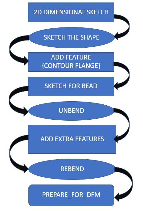
PROCESS STEPS WITH DESCRIPTION
- Make a sketch on the front plane to apply contoour flange so we can create a profile that relevent to the 2D diagram. make sure the dimensions are absolutely similar to the given 2d diagram.
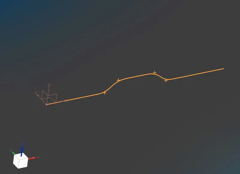
CONTOUR FLANGE
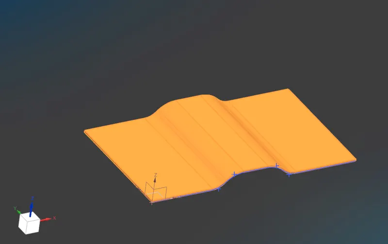
- Create a contour flange based on the previous sketch with appropriate dimensions
thickness = 3mm
NORMAL CUTOUT
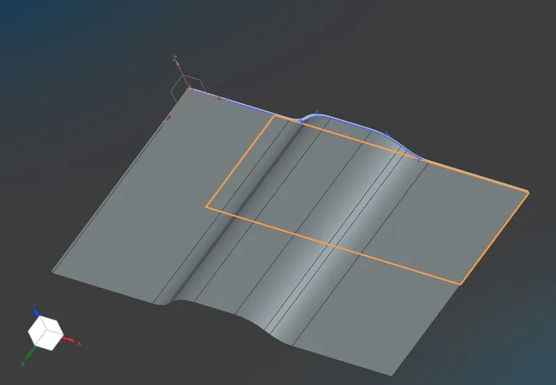
- create a sketch to make a normal cutout. and then cut the unwanted material to have a similar look as the 2d given diagram. the main reason which we use normal cutout command to cut part is the cut will normal to the part cross section.
SKETCH IMAGE
FINAL IMAGE
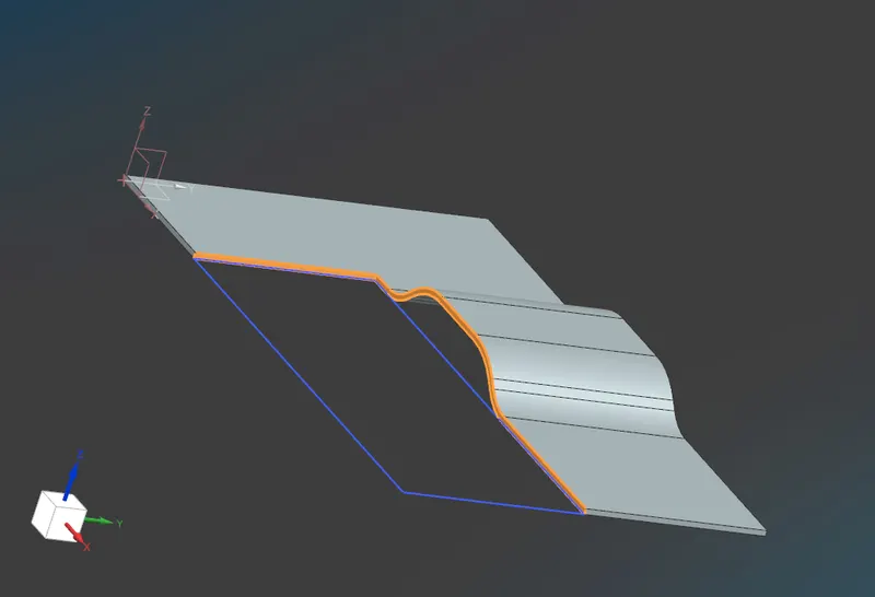
BREAK CORNER
- Use break corner to eliminating the sharp edges from from the part. to get a part as shown in the 2d drawing.
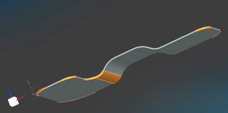
SKETCH
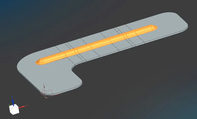
- Draw a sketch for create a bead. bead will increase the stiffness property of sheet metal.
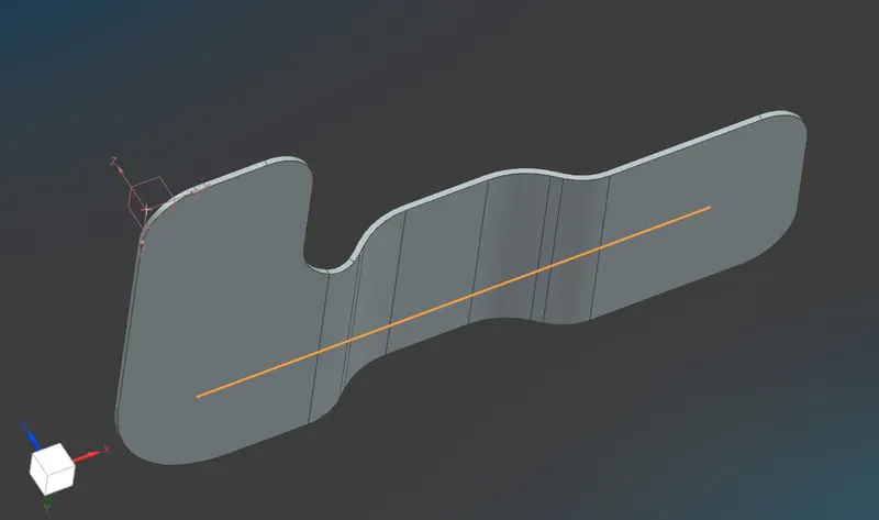
UNBEND
- unbend the sheet metal part to apply a bead.
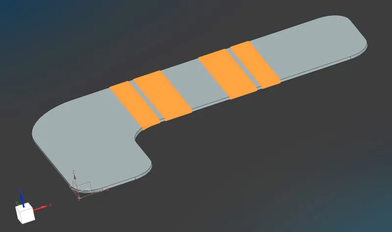
BEAD
- Apply a bead the bead profile will be our last sketch. follow the bead description given tn the 2D diagram.
REBEND
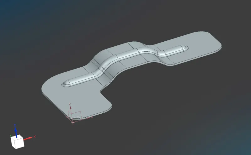
- after successful implementaion of bead then do a rebend it will bring our part back to it's original position.
HOLES
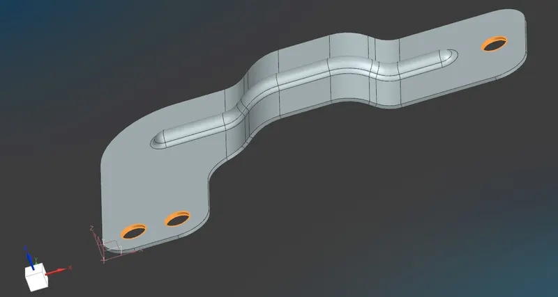
- Add holes on the bracket with appropriate dimension mentioned in the 2d drawing.
- these are the tools which i used to desing a sheet metal bracket.
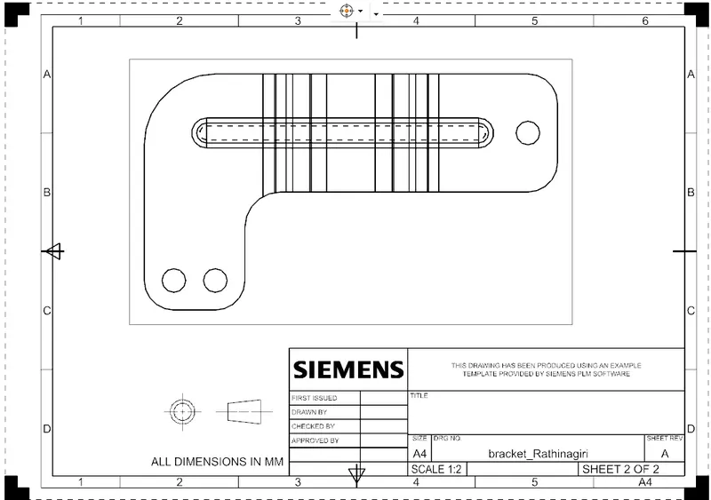
SKETCH DIAGRAM ON DRAWING SHEET
FLAT PATTERN ON SHEET
FRONT VIEW
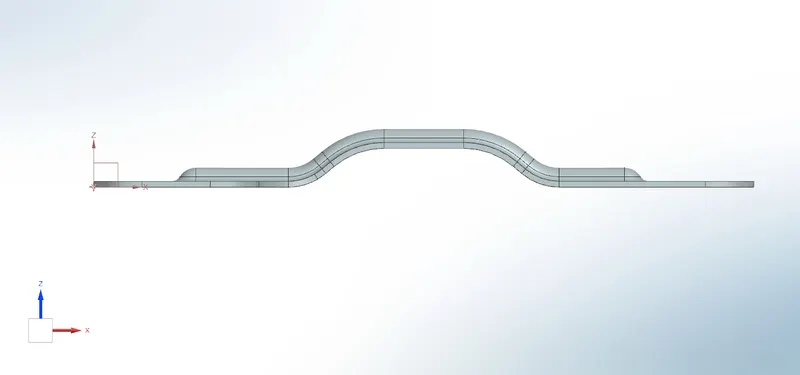
RIGHT SIDE VIEW
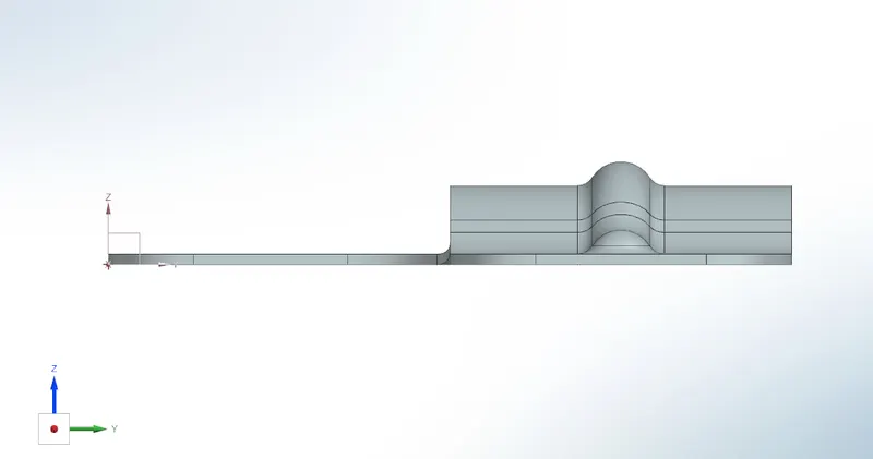
LEFT SIDE VIEW
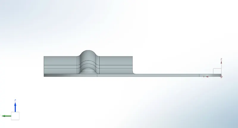
TOP VIEW
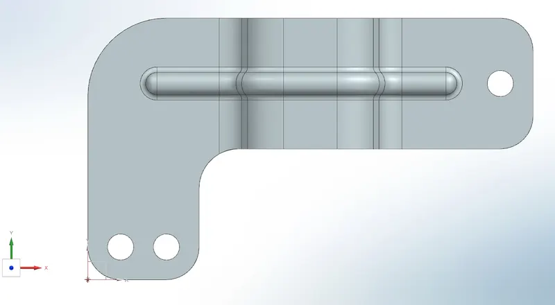
BOTTOM VIEW
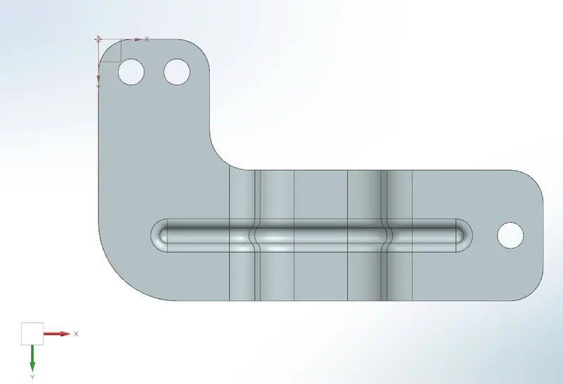
ISOMETRIC VIEW
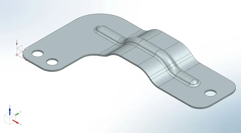
CONCLUSION
- Finally i have successfully designed a sheet metal bracket from a given 2D diagram and in the journey i also learned how to design a part from 2D description.