Advanced Sheet Metal Design Using NX Cad Challenge_2_Box Assembly
Advanced sheet Metal using NX CAD- Box Assembly
Objective
To create the BOX assembly using NX CAD and understand the step by step approach to a Assembly design in NX CAD
Introduction
Sheet Metal is a Comprehensive cold working process for metal sheet (usually below 6mm), including Shearing, punching/ cutting, Folding, riveting, splicing, forming (such as car body).
Types of sheet metal
- Galvanized steel
- Stainless steel
Box assembly has wide application from military use to domestic, based on the weight carrying capacity and conditions it will be used in the material keeps on varying.
Design Methodology (Flow chart)
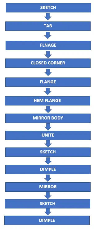
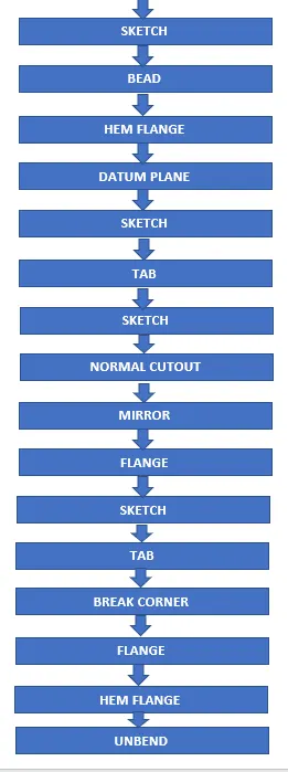
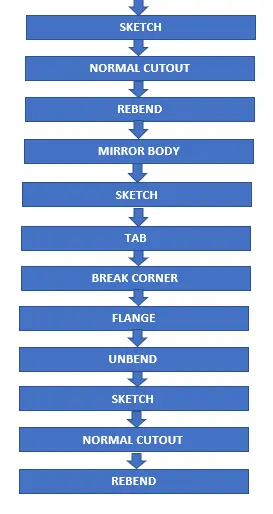
DESCRIPTION
tools
- Sketch- by selecting the required plane sketch is drawn by using geometrical constrains and giving desired dimensions
- TAB- this command is used to extrude a sketch along a specific direction or axis by a giving required thickness (converting 2D sketch to 3D)
- Normal cut-out- this command is used to remove material from the object by using desired sketch profile or curve.
- Bending- as the name suggest this command is used to bend the tab along required line.
- Flange- this command is used to create flange by using edge of TAB or BEND at an angle and length.
- Break corners- this command is used to round the sharp edges.
- Unbend- this command is used to unbend all the adjacent bend sides and other operations.
- Hole- command is used to remove material from the base or required side.
- Dimple- this command is used to create a raised surface on a flat surface in a required shape by creating sketch.
- Bead- this command is used to give additional strength to part.
- Re bend- after doing required operation which is not possible to do in bend state, un bend command is used to bring the initial state which is required.
- Flat Pattern- after Re bending and finishing all the operation flat pattern command is used to flat the sheet metal component which is then used for drafting purpose.
- Mirror- this command is used to mirror a feature or body about a plane.
- Datum- As per the drawing need a new datum plane can be created using one reference
- Break corner- this command is used to round the sharp edges
- Closed corner- this feature is used to close gap between the sheet metal corners.
Select the XY plane and the rectangle as shown in image
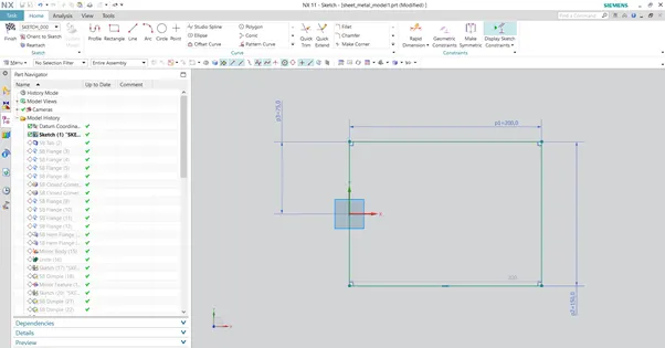
Use the tab command select the rectangle and give the required thickness.
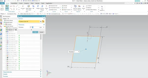
Select the flange command the edge of the tab and draw the flange, repeat the step for opposite side as well.
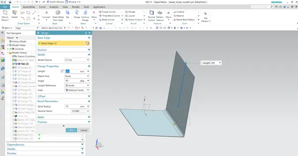
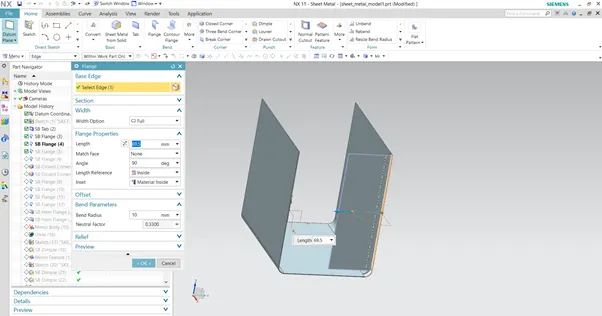
Select the flange command and draw the flange as shown in image, and repeat same procedure for other side.
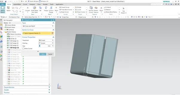
Using closed corner command close the edges of the box.
Select the highlighted edge and draw a flange.
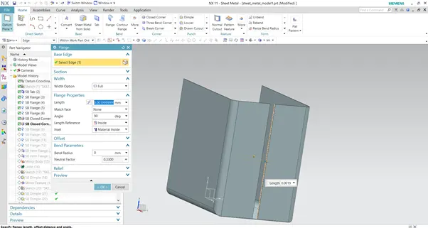
Select the edge as shown in image and draw the flange with required parameters.
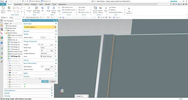
Draw the hem flange as shown in the image selecting the highlighted edge with required parameters, repeat the same step for other flange as well.
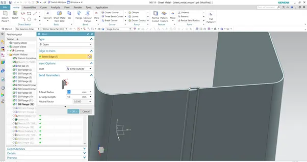
Using mirror body option create the other half of the box.
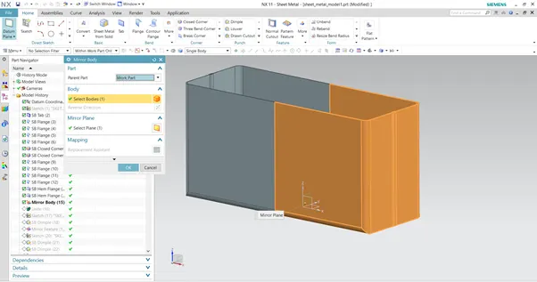
Select the unite option and unite the mirrored body with the original body.
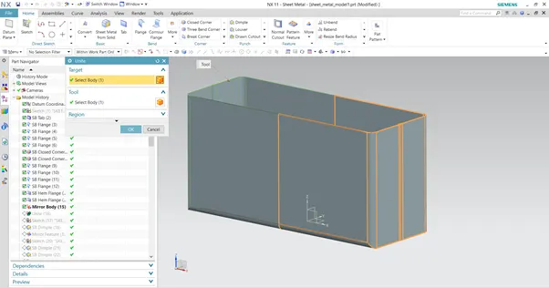
Select the sketch option and draw a sketch as shown in image.

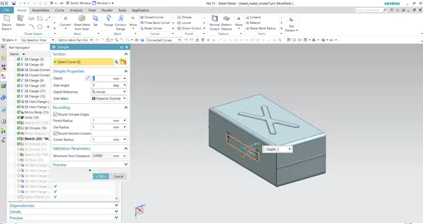
Select the dimple command and select the sketch which was drawn earlier and create the dimple by giving the required parameter.
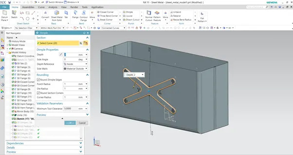
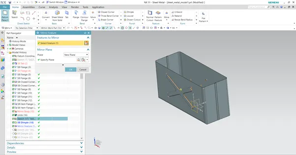
Using the mirror feature option mirror the dimple on the other flange as well.
Select the sketch command and draw the rectangle.
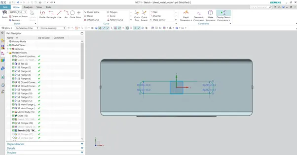
Click on the dimple command and select the sketch give required parameter and create dimple.
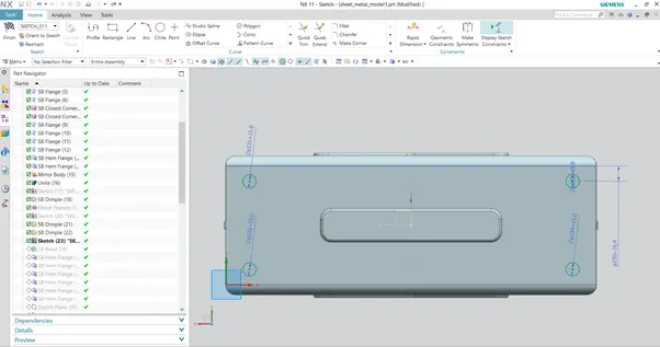
Select the bottom surface and draw the circle’s as shown in the image.
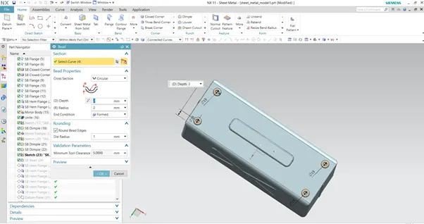
Select the bead command, select the sketch give the required parameters and create the bead as shown the image.
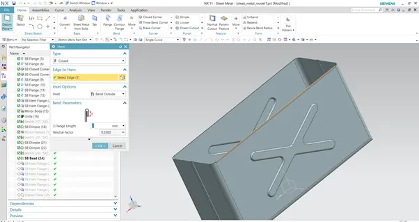
As shown in the select the highlighted edge and create the hem flange, repeat the same step for the all the open edges.
Create a new datum plane by taking original XY plane as reference.
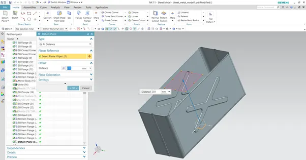
Draw a rectangle with the given dimensions on the newly created datum plane.
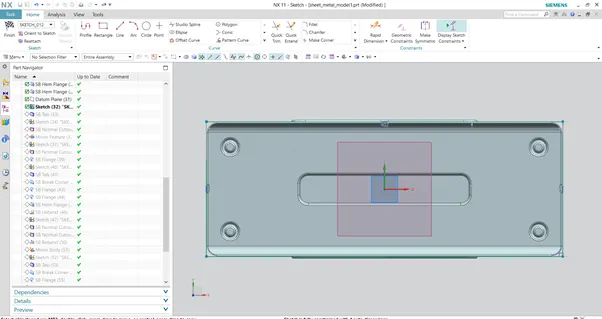
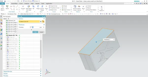
Create a tab on the new datum by selecting the sketch which is drawn on datum plane.
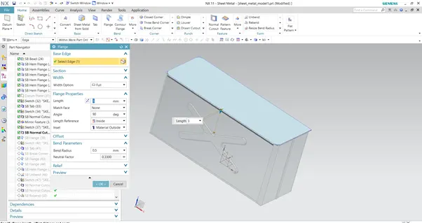
Select the highlighted edge and create flange with required dimensions.
Create a sketch by selecting the surface as shown in the image, draw a rectangle with the given dimensions.
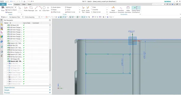
Click on the tab option and select the previously drawn rectangle and create tab with the required thickness.
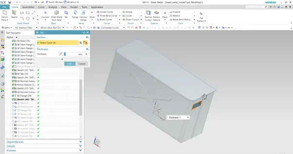
As shown in the image select the lower left corner edge of the tab select corner break option and give the required radius.
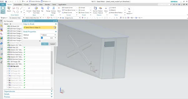
Click on the flange option, select the highlighted edge and create a flange at required angle and length.
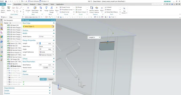
Click on the flange option and create a new flange on the existing flange by giving angle and length as shown in the image.
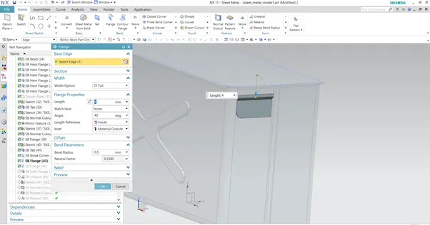
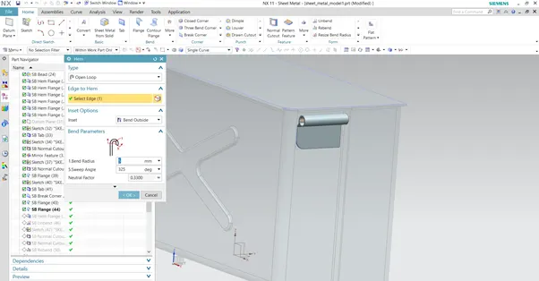
Click on the hem flange option, select the open loop type give the angle required and create the hem as shown in the image.
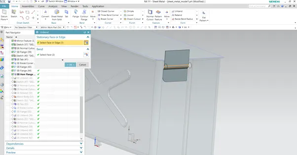
Unbend the flange shown in the image.
Click on the sketch option on the surface of unbend flange and draw the sketch as shown in the image.
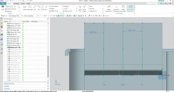
Select the normal cut-out option, and remove the material as shown in the image.
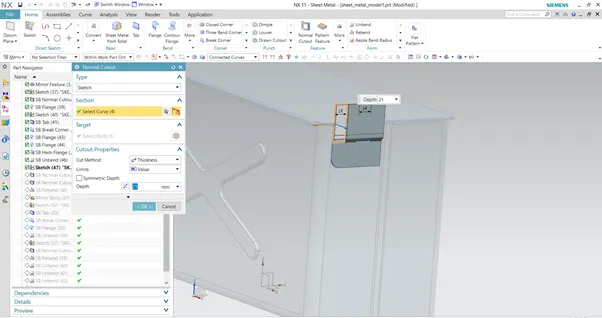
As shown in the image re bend the flange.
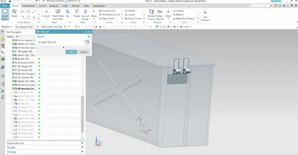
As shown in the image mirror the feature to other side.
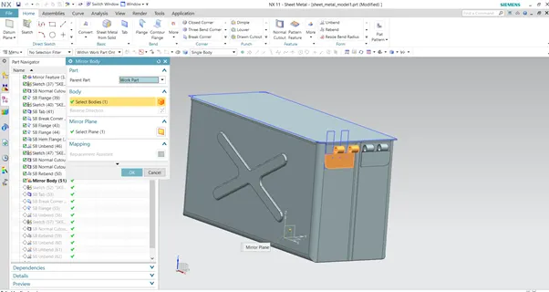
Draw the rectangle as shown in the image with required parameters.
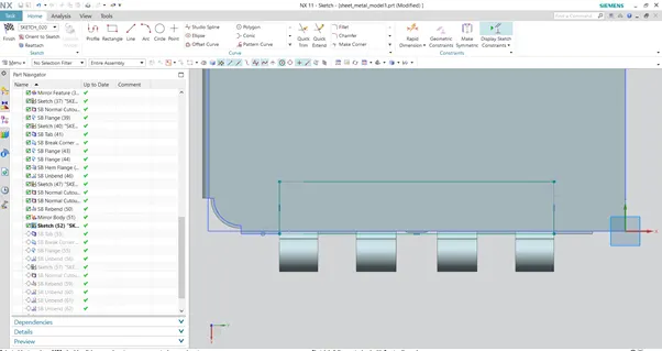
By selecting previously drawn rectangle create the tab.
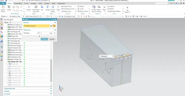
As shown in the image select edges and apply break corner feature with required radius.
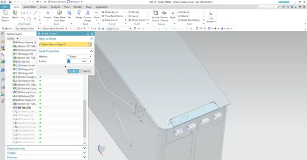
As shown in the image select the highlighted edge and draw the flange with required angle and length.
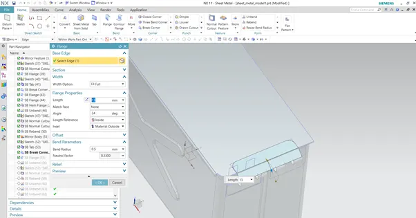
Unbend the flange as shown in the image.
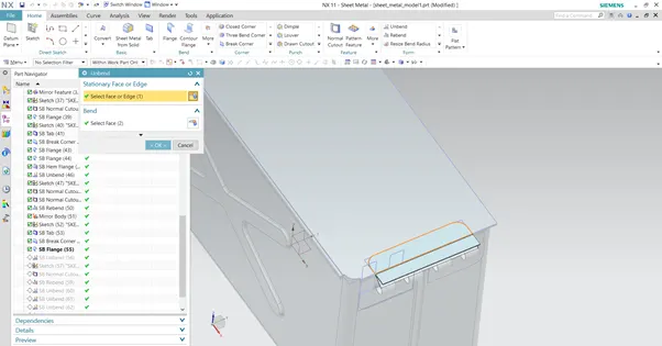
Select the surface of unbend flange and draw the sketch as shown in the image.
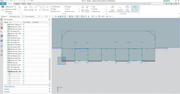
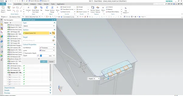
Using normal cu tout remove the unwanted material as shown in the image.
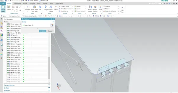
Re bend the flange as shown in the image.
Box Assembly views
Front view
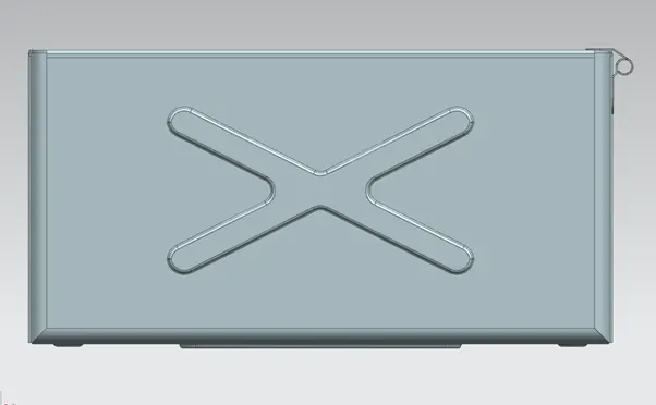
Side view
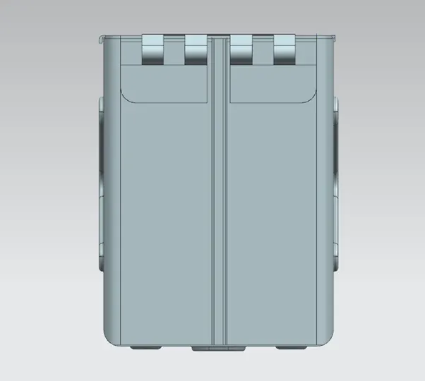
Top view
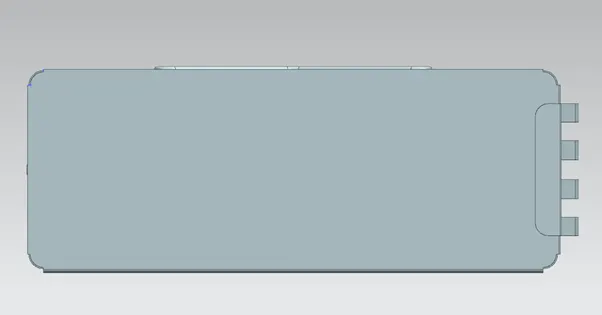
Isometric view
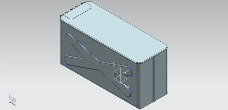
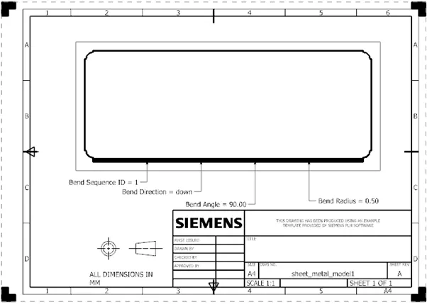
Drawing View
Box
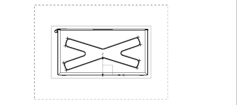
Box lid
Conclusion
Thus Box Assembly using NX CAD is completed and drafting of the different using NX drafting workbench is done.