Advanced Sheet Metal Design Using NX Cad Challenge_5_Odd Shaped Enclosure
TITLE: Odd shaped enclosure using NX CAD
OBJECTIVE: To design sheet metal part for odd shapes as per the workflow procedure by using NX-CAD software with suitable commands to achieve the final product as per the inputs.
INTRODUCTION: NX-CAD is one of the powerful design tools designed by Siemens to design various products from 2D to 3D by using various platforms (like modelling, sheet metal and surfacing etc..) with suitable commands to achieve the final product.
Based on this I going to design a product named as odd shaped sheet metal part design as per the workflow procedure.
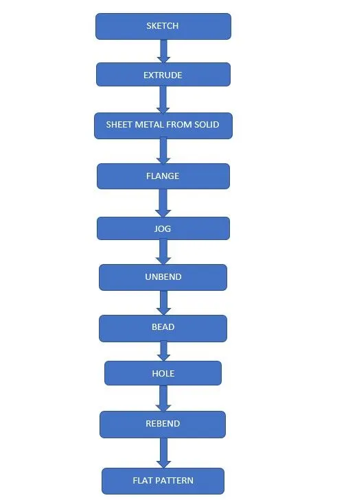
DESIGN METHODLOGY:
DESCRIPTION:
SKETCH: It is the 2D representation of the model with respect to the plane or view.
EXTRUDE: Creates a 3D solid from an object that encloses an area, or a 3D surface from an object with open ends.
SHEET METAL FROM SOLID: Builds a sheet metal model that takes its shape from a collection of planer faces. After using this feature the solid body will be converted into a sheet metal.
FLANGE: Sheet metal flange features consist of a face and bend connected to an existing face along a straight edge. Flange features are added by selecting one or more edges and specifying a set of options that determine the size and position of the material added.
JOG: Modifies the model by lifting material on one side of a sketch line, adding a flange between the two edges.
UNBEND: Flattens a bend and the material adjacent to the bend.
BEAD: Lifts material along the counter of a sketch that simulates a stamping tool.
HOLE: Adds a hole to one or more solid bodies in a part or assembly.
REBEND: Restores an unbend features to its previous bent state, along with any features added after the unbend feature.
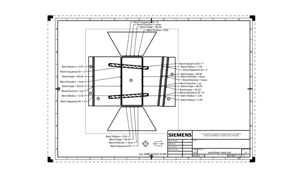
FLAT PATTERN: Flat pattern tool is used to automatically create a flattened version of a sheet metal part and prepare model for manufacturing. The flat pattern feature remains the last feature in the model tree and maintains the flat model view.
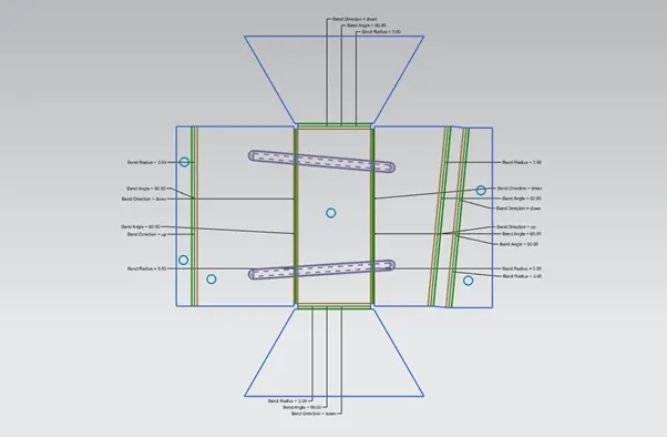
STANDARD VIEWS OF MODEL:
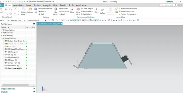
FRONT VIEW
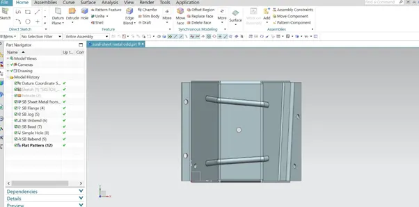
TOP VIEW
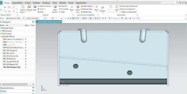
SIDE VIEW
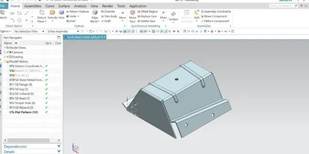
ISOMETRIC VIEW
DRAFTING: Drafting is a term that refers to creating technical drawings that communicate the how to constructed or features.
CONCULSION:
By this challenge I came to know about the application of various commands like extrude, solid to sheet metal, jog, and flat pattern to achieve the final product as per inputs.