Advanced Sheet Metal Design Using NX Cad Challenge_5_Odd Shaped Enclosure
week-5 challenge:
Advanced sheet metal design using a nx cad:
Enclosure:
OBJECTIVE:
To create a sheet metal product using a NX cad.
by using a tab,extrude, flange,bend, hole and bead commands are used to create a product.
INTRODUCTION:
sheet metal:
sheet metal is the metal part which has the thickness less than the .25inch(6mm).
this materials commonly used was stainless steel, aluminium, copper and mild steel etc.
appilcation of sheet metal in household components, electrical components and more.
NX Cad:
siemen Nx Cad is the software used to create a part model, drafting and sheet metal products.
it is also called as "unigraphics" initially.
it is the most commonly used industrial software.
Design Methodology:
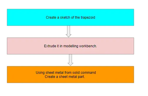
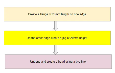
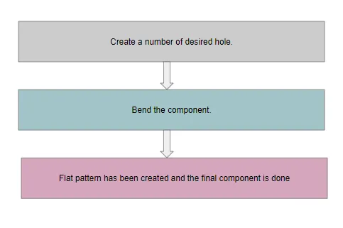
Description: .
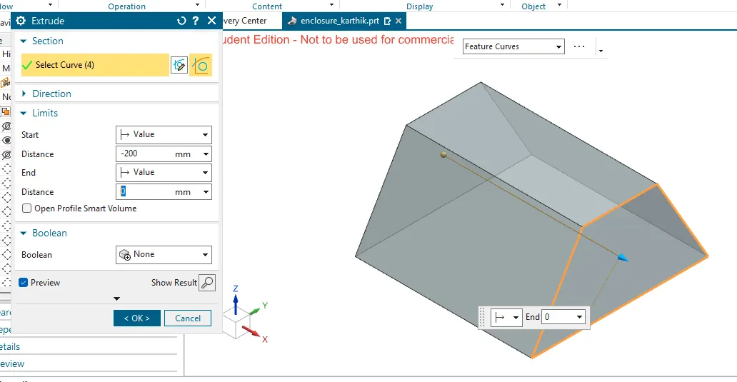
first create a given sketch and extrude in solid modelling with 200mm in modelling workbench.
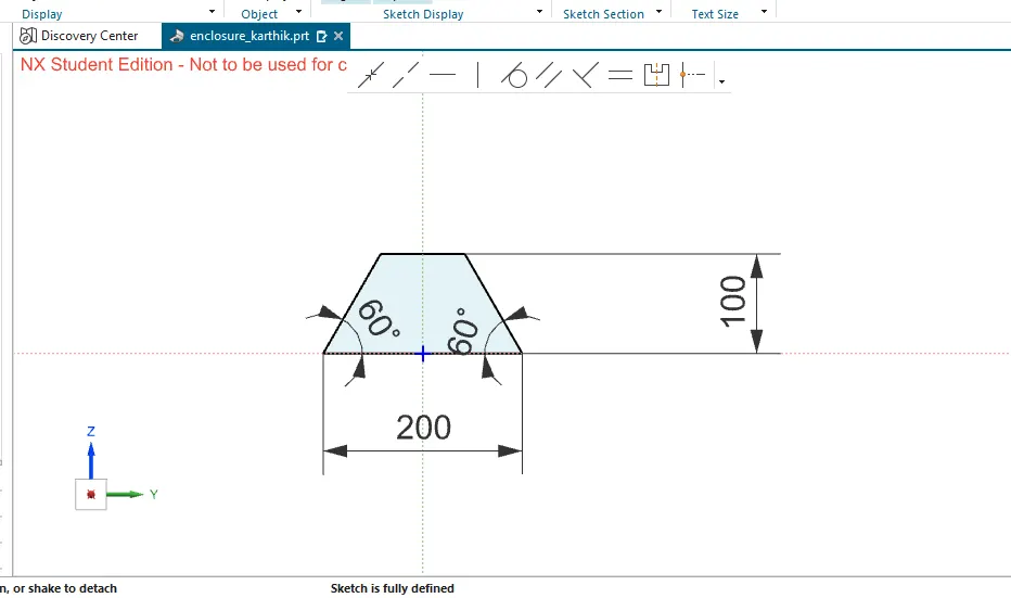
extrude in modelling workbench.
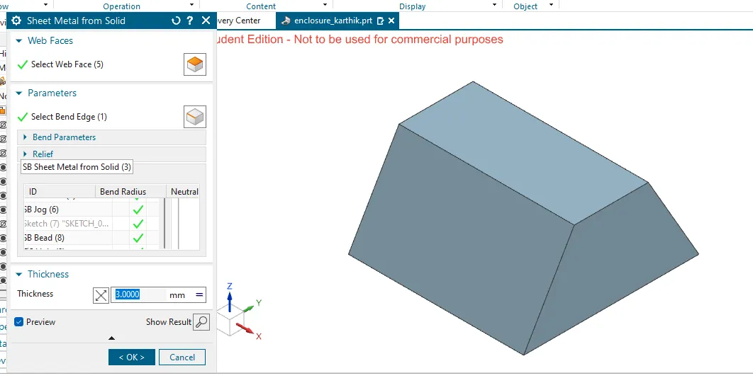
then in sheetmetal workbench, create a sheetmetal from solid using this command.
with the face as the side and the bottom.
bend edge as edge.
flange:
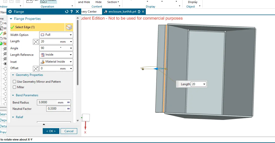
flange is similar like a bend, the differnece is here , the sketch is not provided.
to create a flange select the edge of the part and provide the angle, length of the flange.
unbend:
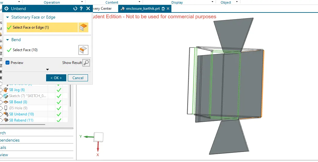
unbend command is used stretch the part along the flat plates.
the sheet metal component is flatten and provide the size of the sheet metal blank.
here it shows the unbend command.
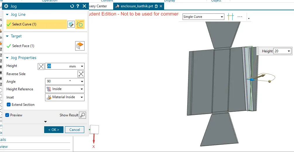
jog:
create a sketch with a required line.
then by using the jog command, curve as sketch and the face as face to jog.
bead:
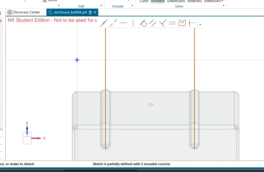
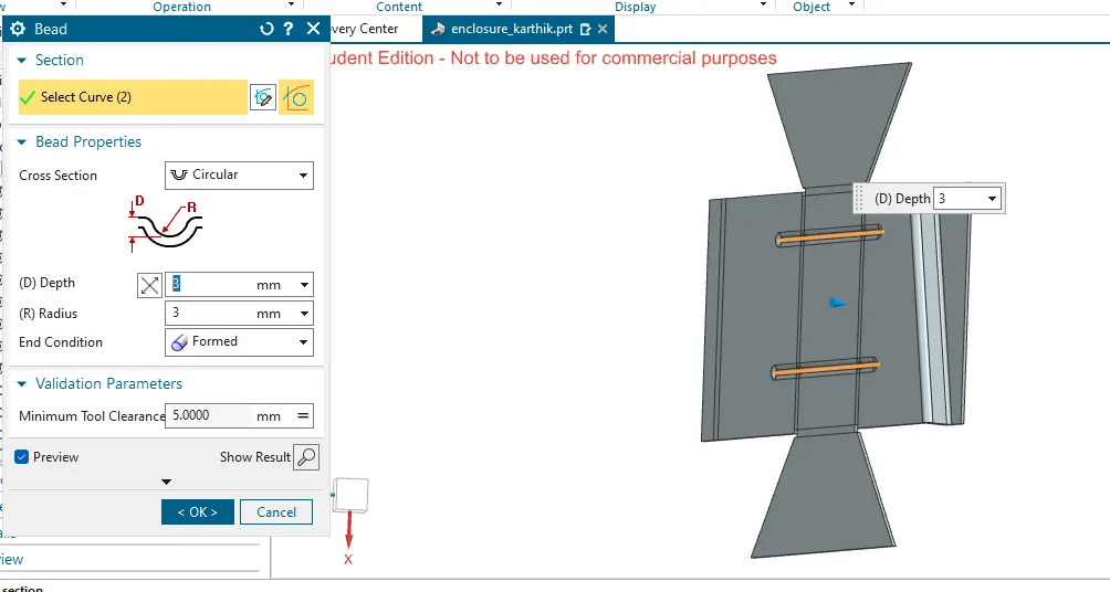
create a sketch of the required dimension for bead a line is drawn.
then give the depth and radius for bead.
holes:
hole command is used to create a hole on the sheet metal.
for this a point was needed to create a hole.
then after creating a point, then provide a hole diameter in mm.
depth, tip angle etc.
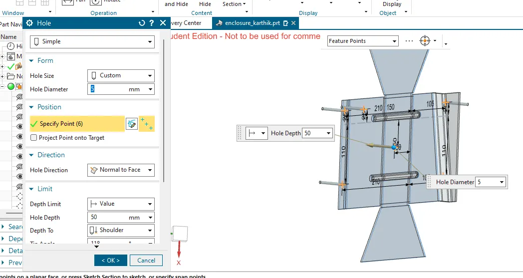
after creating hole, bend the component to get the final output.
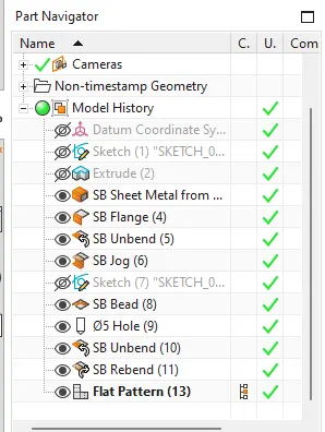
part navigator:
flat pattern:
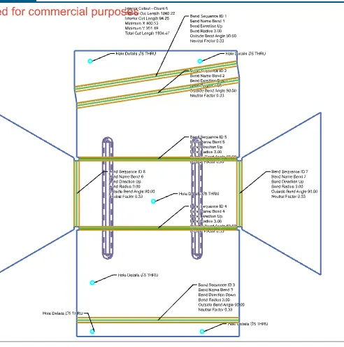
by using a flat pattern.the flat shape of the component is obtained.
it also shows what are all the operation is to be done on the sheet metal blank to obtained the final shape of the component.
here, below shows the falt pattern with the bend, hole, cutout etc.
All views:
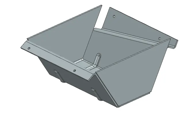
isometric view:
conclusion:
Here a detailed report on Sheet Metal Component with good explanation on Sheet Metal modelling tools applied throughout the modelling of Sheet Metal Casing is done.
note:
the part file is attached below.
===================================================================================================================