Advanced Sheet Metal Design Using NX Cad Challenge_5_Odd Shaped Enclosure
Advanced Sheet Metal Design using NX CAD
#4 Odd Shaped Enclosure
Aim -
Create the odd shaped enclosure according to the given instructions.
Introduction -
Siemens NX provides a set of tools within it that allows for simple and fast design of sheet metal parts. It also incorporates material & process information and sheet metal-specific modelling features like bends, flanges, tabs, cutouts, beads, dimples, louvers, corner, edge treatments, patterns, etc. All these features eases and enhances the design procedure & productivity.
Its also allows to convert solid models to sheet metal components, and create sheet metal parts that enclose other components. All common dimensions can be set as default for ease of work. Sheet Metal products are used in almost all industries, thus design of needed components are made easier with CAD softwares such as Siemens NX.
Design Methodology -
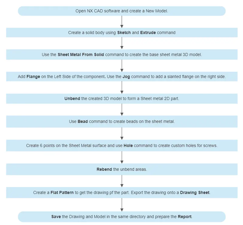
Features used in modelling -
- Sketch :It is basic command to draw 2D model
Mirror Curve mirrors the drawing in the sketch with respect to an axis/plane. - Extrude :It creates a feature by extruding a section/profile of a sketch along a vector.
- Sheet Metal from Solid :It builds a sheet metal model with respect to the planar faces and edges. This command is used to convert the solid body into a sheet metal body.
- Jog :It modifies the model by lifting material on one side of a sketch line, adding a flange between the two sides. This helps to create flanges on surface that could have a slanted profile.
- Flange : Adds flanges to the edges selected. Angle between main surface and length of the flange can be provided.
- Unbend : Used to flatten the 3D sheet metal model.
- Bead : Lifts the material along a sketch, this also stimulates a stamping operation.
- Hole : Used to create specific types of holes for screws. The threading, boring, etc can be provided separately.
- Rebend :Rebends the part that was used in unbend command.
- Flat Pattern: Creates a flat pattern of the feature with all the information on the dimensions.
- Drawing : It’s used to create drafted drawings of selected part/product.
Base Viewcreates the main view on the drawing sheet.
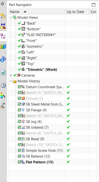
Design Stucture Tree -
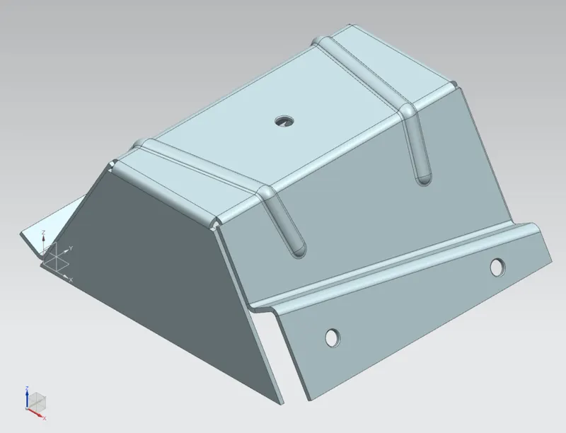
Result -
Isometric View :
Right side View :
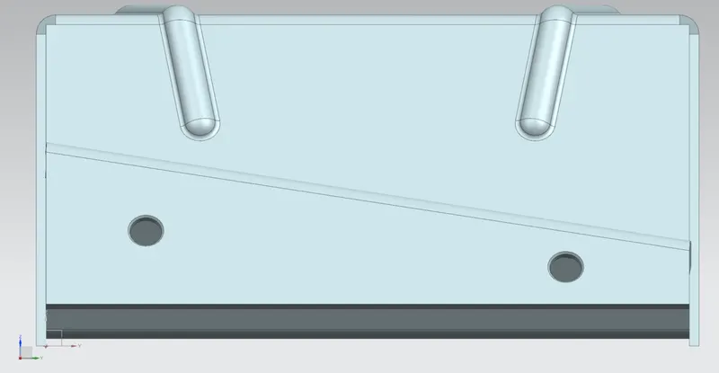
Left side View :
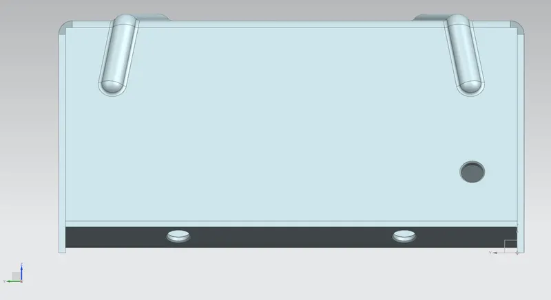
Front View :
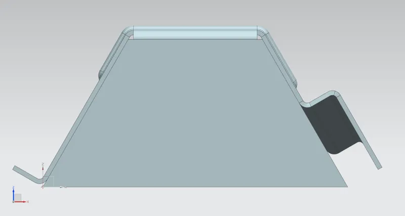
Top View :
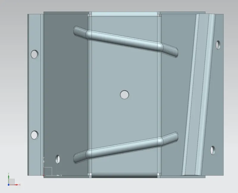
Detailed Drawing of 2D sheet metal part :
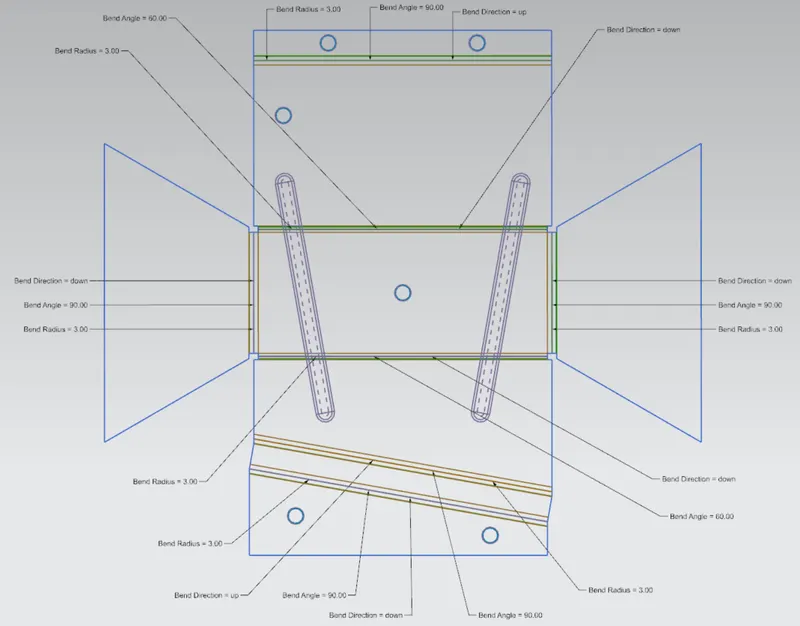
Conclusion -
The model is prepared according to the and the drawing is also created.