Advanced Sheet Metal Design Using NX Cad Challenge_5_Odd Shaped Enclosure
Creating Odd-Shaped Enclosure
Objective: To create the Odd shaped enclosure using the NX cad sheet metal module.
Design methodology / approach:
- Create the solid extrude body from the given dimensions
- Switch from the Modeling section to the sheet metal section and select Sheet metal from the solid feature. Select the web faces and bend faces. Set the thickness of the sheet to 3mm and bend the radius to 3mm as well.
- As your sheet metal body is created as a wrap over it, create a flange on one side of the body.
- Create a jog that is at a certain angle with respect to horizontal as shown in the below part images.
- Unbend the sheet body and using the hole feature create the holes referring to the input parameters.
- After the holes are completed use insert the beads on the top face of the component to provide the strength as shown in the below image.
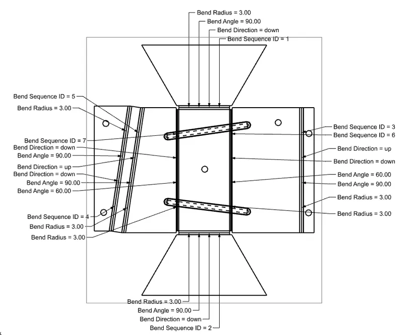
- Rebend your work and your wrap-around sheet body is created, Next step is to create the flat pattern for studying the bend parameters and checking for manufacturing feasibility.
- Go to the flat pattern option and select the upward face and in orientation set to the 'select edge' and select your edge.
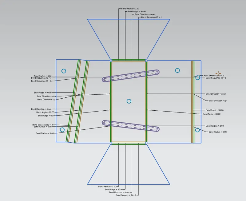
- The flat pattern feature is visible in your feature tree but to visualize it go to 'replace view' and select the FLAT PATTERN as your control view and your flat pattern with bend parameters will be visible on your screen.
Feature information:
Use the Sheet Metal from Solid command to create a sheet metal part using a solid to model it. The solid represents the inner void of an enclosure. You select the faces from the solid to be panel (web) faces and edges between the faces to be bend regions. You specify bend properties or use the ones you established in the Sheet Metal Preferences dialog box. NX creates the model based on your inputs. You can then treat this part as you would any other sheet metal part.
Use the Flange command to create a single flange instance or multiple instances by selecting single or multiple base edges.
Use the Unbend command to unbend a portion of the part to construct cutout features, hole features, or deform features across a bend. You can later reform the bend to represent the true formed state of the model.
Use the Bead command to lift material along the contour of a sketch that simulates a stamping tool. Beads can also be created to stiffen sheet metal parts.
Use the Rebend command to return an unbend feature to its previous bent state. Any features added after the unbend operation are properly repositioned during the rebend operation.
Use the Normal Cutout command to cut material by projecting a sketch onto the model and then cutting perpendicular to the faces intersected by the projection
Jog constructs two 90-degree bends and adds material to them to jog to a planar face of a part. The profile for a Jog feature must be a single linear element and can only be constructed across a planar face. The jog can be minimal, for example, a slight offset or step to provide clearance or rigidity to a part.
Use the Flat Pattern command to create a 2D representation of the flattened 3D sheet metal part.
You can:
-
Create a flat pattern from a formed sheet metal body or from flat solids.
-
Control orientation of the Flat Pattern view for the upward face having non-linear edges. To do this, you need to specify a CSYS while defining the orientation.
-
Represent holes smaller than or equal to a specified diameter value as countermarks in the flat pattern view. This is useful when holes need a different manufacturing process.
-
Create an associative flat pattern fixed at the current timestamp. This helps you create a flat pattern view at the intermediate stage of the part design.
-
Edit the bend properties, such as bend sequence and bend names, using the Bend List command after making the Flat Pattern view the active view.
-
Get the lengths of the exterior boundary and interior cutouts of a flat pattern.
VIEWS:
1. Isometric View
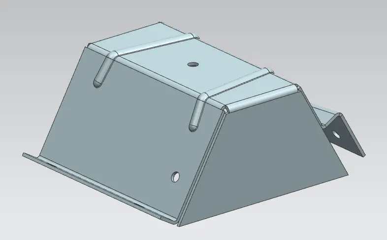
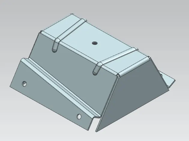
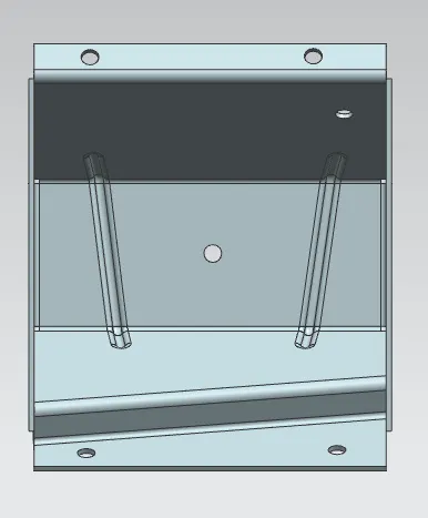
2. Top View and Bottom Views
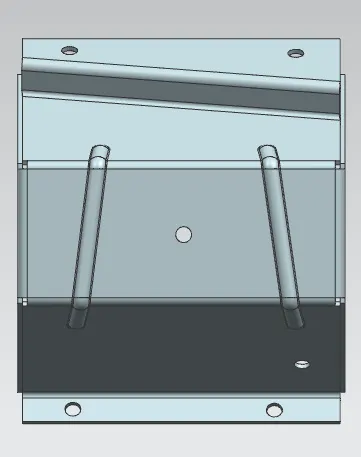
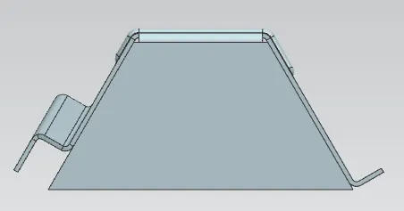
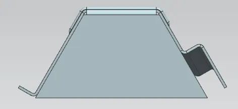
3. Side views
4. Flat Pattern
Drawing