Advanced Sheet Metal Design Using NX Cad Challenge_5_Odd Shaped Enclosure
* Title : Report on Sheet Metal Component with good explanation on Sheet Metal modelling tools applied throughout the modelling.
*Objective : Detailed report on Sheet Metal Odd Shaped Enclosure. And with a good explanation on Sheet Metal modelling tools applied throughout the modelling.
* Introduction :
* Sketching the model with given parameters.
* Generating a solid part by extrude option .
* Wraping the solid body with sheet metals and adding features beands.
*Unbending the part to add holes etc and rebend the surface ,to create a flat pattern.
* Design methodology :
| Opening NX . | |
| Sketching . | |
| Generating the part . | |
| Converting solid part to sheet metal | |
|
|
| Using unbend and rebend for holes,bends. | |
| saving and closing the file . |
* Description :
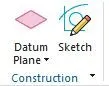
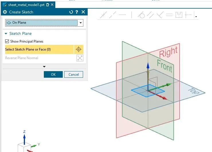
* Open NX ,click to sketch and select the plane .
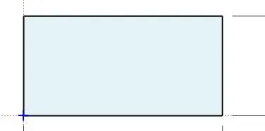
* In sketch tool ,click to rectangle and sketch of dimension 200mm by 100mm.
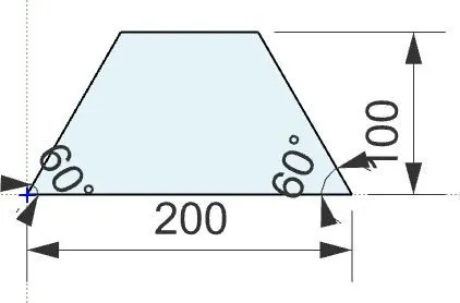
*Furthermore, change the angles of rectangle as show below .
* Sketch : It is process of drawing the outline of a model with required geometry parameters .

* Sketch after drawing a rectangle :
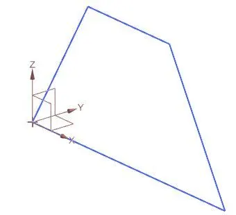
* Sketch after Changing angles of rectangle :
* Performing of extrude Option :
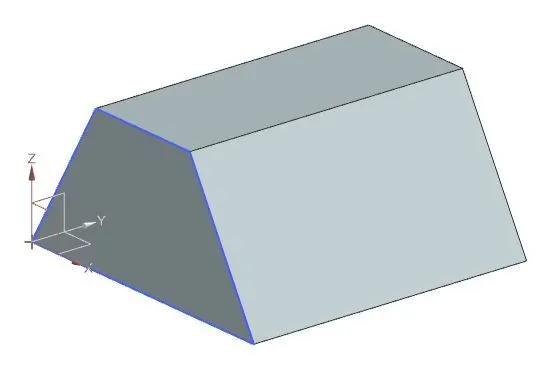
* Extrude : The process ,it Generates a solid body with specified distance with respect to sketch are known as extrude.
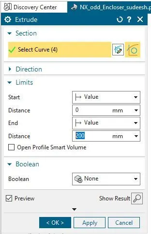
* Select extrude from tool bar and select the sketch.
*Give the distance as 200mm as shown below .
*Keeping the start value as 0mm and the end value to 200mm distance as shown below .
* Model before performing extrude :
* Model After performing extrude :
* Converstion of solid to sheet metal:
* solid to sheet metal : The process that a solid part is converted into sheet metal,as selecting the surface which is connnected to the selected surface specify the thickness ,this solid part gets to sheet metal part .
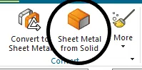
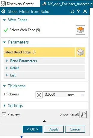
* From convert tool bar select sheet metal from soild .
*Now,select the solid surface which need to be converted it into sheet metal.
* Select the surface and the connected surface inorder to develop into sheet metal.
* Give the thickness as 3mm as shown below ;
*Also parametres , select the adjecent any one edge of solid ,furthermore the adjecent sides gets converted into sheet matal part.
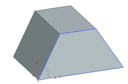
* solid model before converting :
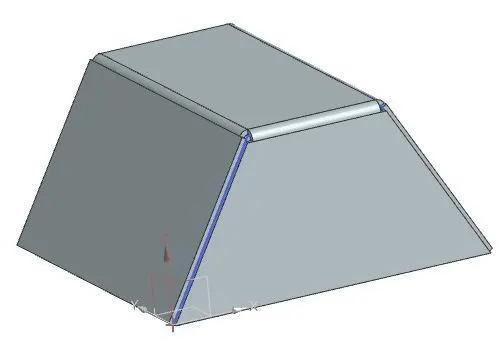
* solid model After converting :
* Creating flanges :
Flanges : It is Process that adds a flat surface at angle and bends the surface accordingly.
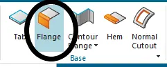
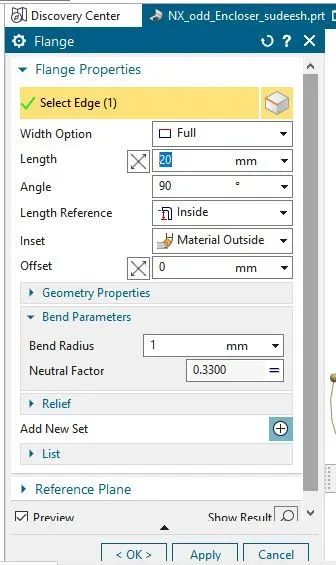
* Click to flange from tool bar and select the edge .
* Now, Give the required length 20 mm as shown below .
* Selecting the width option as full and angle 90 with the length reference inside,inset as material outside as show ;
* Model before performing flange :
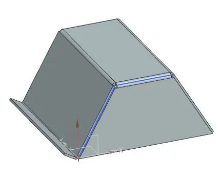
* Model After performing flange :
* Performing of jog Option :
* Jog : This is a process that lifts a material at one side of sketch line and adds the flange between the two sides .
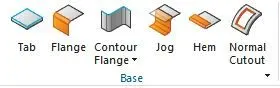
*Select jog from base tool bar and select the surface where the sketch need to be drawn.
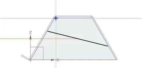
* Draw a line for jog and click to finish .
* Give the height of jog as 20mm ,hieght reference as inside and the inset as material inside .
*After sketch ,select this sketch and click ok as shown below ;
*Select the sketch in jog card and draw a sketch as shown below.

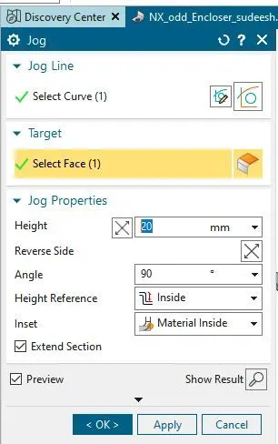
* Model before performing jog :
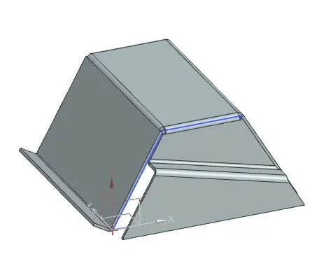
* Model After performing jog :
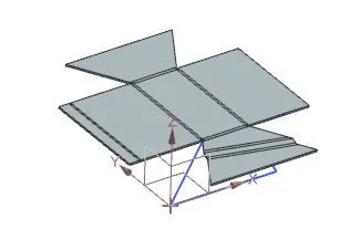
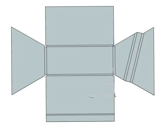
* Performing of unbend :
* Unbend : The process that flatten the bends and the material adjecent to the bend.
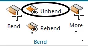
* From bend tool bar select ubend and drag the surface which provides a flattern sheet metal .
* Finally click ok as shown below ;
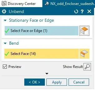
* Model before Performing unbend :
* Model After Performing unbend :
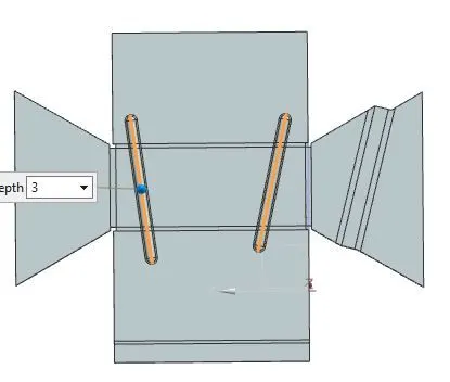
* Performing of Beads :
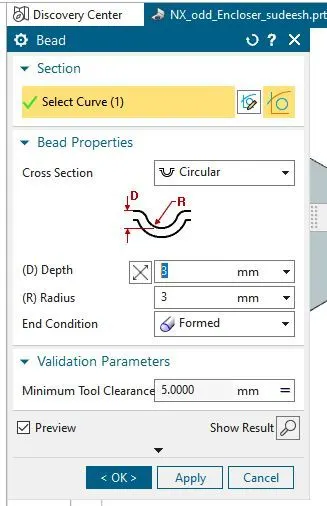
Beads : The process that creates a surface lifts with parameters are known as beads .
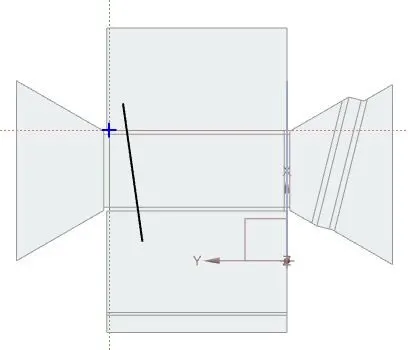
* select beads from tool bar and click to surface where the beads needs to be drawn .
* Specify the bead properties as cross section as circular and depth and radius as 3mm as shown below;
*Model after drawing the sketch :
* Model before performing beads :
* Model After performing beads :
* Performing of holes :
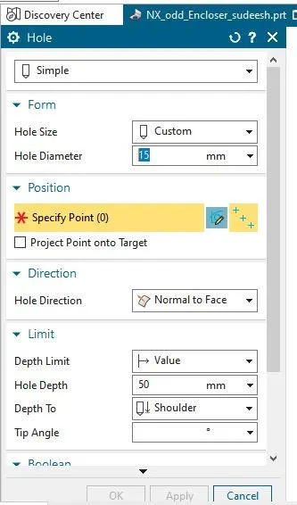
Holes : The process which extrudes into the surface with spcified depth and radius are known as holes .
*Select holes from tool bar and select the surface where the holes has to be done .
* Giving the proper parameters as shown below as hole diameter as 15mm,hole direction to normal to face and depth as 50mm.
* Specify the points on the surface to hole and click ok .
* Model before performing beads :
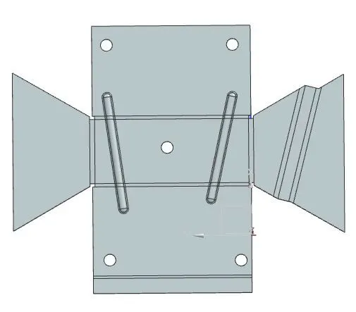
* Model After performing beads :
* Performing of Rebend :
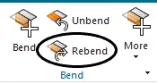
Rebend : It Restores the unbend to its previous bend along with any features added after the unbend features.
* Select the rebend from bend tool bar.
* Now ,drag the complete unbend part and click ok as shown below ;
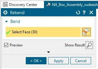
* Model before Rebend :
* Model After Rebend :
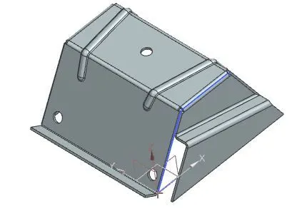
*Isometric View :
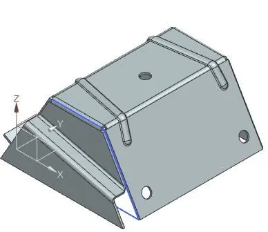
* Fornt View :
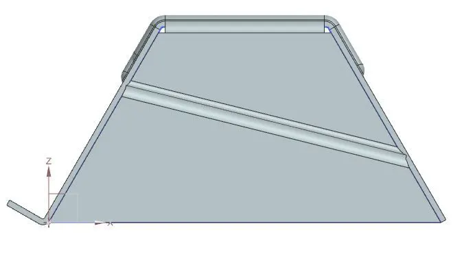
* Side View :
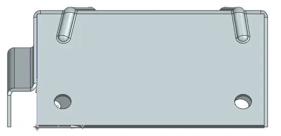
* Top view :
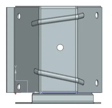
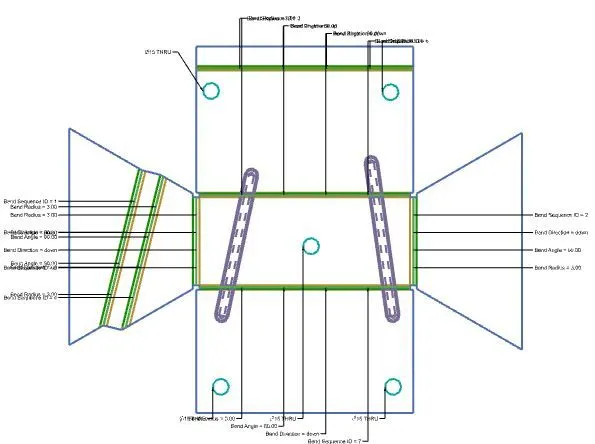
* Creation of flat pattern :
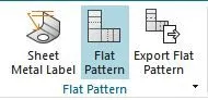
Flat pattern : This creates a flat pattern feature from the formed sheet metal part .
* From flat pattern tool bar select flat pattern .
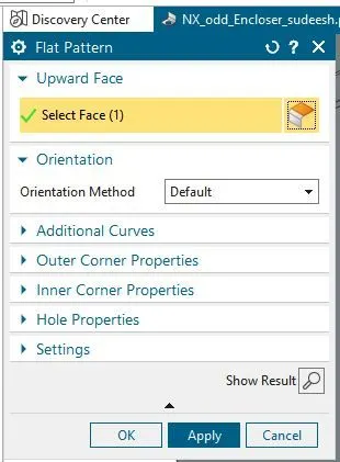
*Now,drag the complete sheet metal part and click ok as shown below .
* To check the created flat pattern ,go to feature tree and dropdown to model views.
* Moreover ,click to flat pattern and check those parametrs as shown below ;
*Model after performing Flat pattern :
Conclusion : using Nx we can perform or generate the solid part and then it cab converted it to sheet metal as required with the features required .