Advanced Sheet Metal Design Using NX Cad Challenge_5_Odd Shaped Enclosure
ODD SHAPED ENCLOSURE
Objective: To design the given sheet metal component "Odd shaped Enclosure" as per the given dimensions and creating the flat pattern by using the Siemens NX CAD software.
Introduction:
- The given is a solid component that should be converted into sheet metal component using the commands.
- The component given is for making practice and to get familiar with the convert to sheet metal wizard commands.
- The component has to be designed with the given dimensions and if the dimensions are not given then we have to consider our own dimensions.
Design methodology:
1. Creation of Solid body
2. Wrapping the solid body with sheet metal
3. Adding the features
4. Unbending for adding extra features(if needed)
5. Rebending the unbend areas
6. Creation of Flat pattern
Features/Tools used:
1. Sketch: It creates a sketch in the current application. Use the direct sketch tools to add curves, dimensions,constraints, etc.
2. Extrude: This tool creates a feature by extruding a section along a vector.
3. Sheet metal from solid: This tool builds a sheet metal model that takes its shape from a collection of planar faces.
4. Flange: This feature adds a flat flange at an angle to a planar face and adds a bend between the two.
5. Jog: This tool modifies the model by lifting material on one side of a sketch line, adding a flange between the two sides.
6. Unbend: It flattens a bend and the material adjacent to the bend.
7. Rebend: This feature restores an unbend feature to its previous bent state, along with any features added after the unbend feature.
8. Bead: This feature lifts the material along the contour of a sketch that simulates a stamping tool.
9. Hole: This feature adds a hole to one or more solid bodies in a part or assembly with options for counterbored, countersunk and threaded.
10. Flat Pattern: This tool creates a flat pattern feature from the formed sheet metal part.
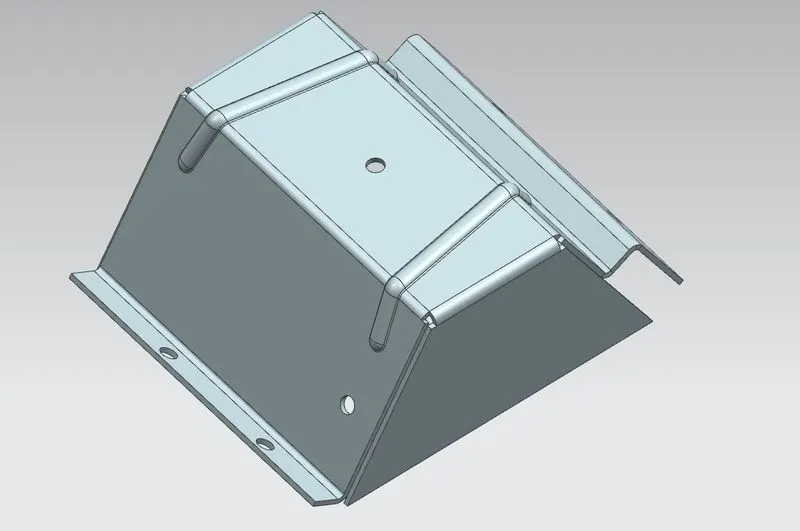
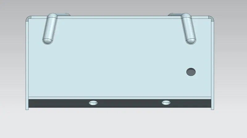
Trimetric view Front view
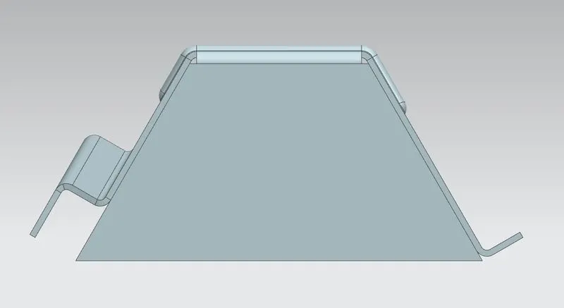
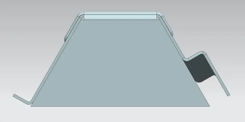
Left view Right view
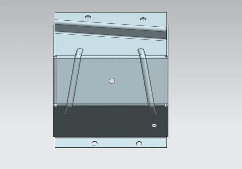
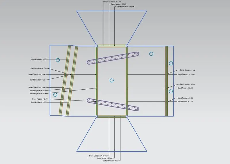
Top view Flat Pattern
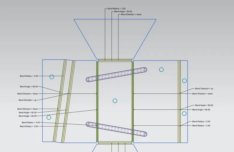
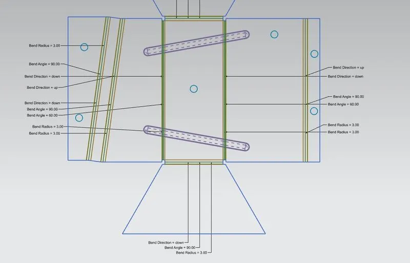
Flat Pattern_1 Flat Pattern_2
Conclusion: So the given solid component is designed and converted into sheet metal component as per the given dimensions and also flat pattern is created as above by using the Siemens NX CAD software.