Advanced Sheet Metal Design Using NX Cad Challenge_5_Odd Shaped Enclosure
ODD SHAPED ENCLOSURE DESIGN
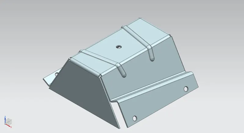
OBJECTIVE
To design an odd shaped enclosure and under stand the various commands in the sheet metal application in Siemens NX software.
INTRODUCTION
In this project we are going to learn about the different manufacturing processes that can be performed on a sheet metal. There is a factor known as the "K" factor which aids us in giving appropriate bend radius to the available sheet metal thickness. The K-factor comes from the ratio of the neutral radius divided by the thickness of the material on prepared charts and has a value between 0.3 and 0.5.
Sheet metal is metal formed by an industrial process into thin, flat pieces. Sheet metal is one of the fundamental forms used in metalworking, and it can be cut and bent into a variety of shapes. Countless everyday objects are fabricated from sheet metal. Thicknesses can vary significantly; extremely thin sheets are considered foil or leaf, and pieces thicker than 6 mm (0.25 in) are considered plate steel or "structural steel".
DESIGN METHODOLOGY
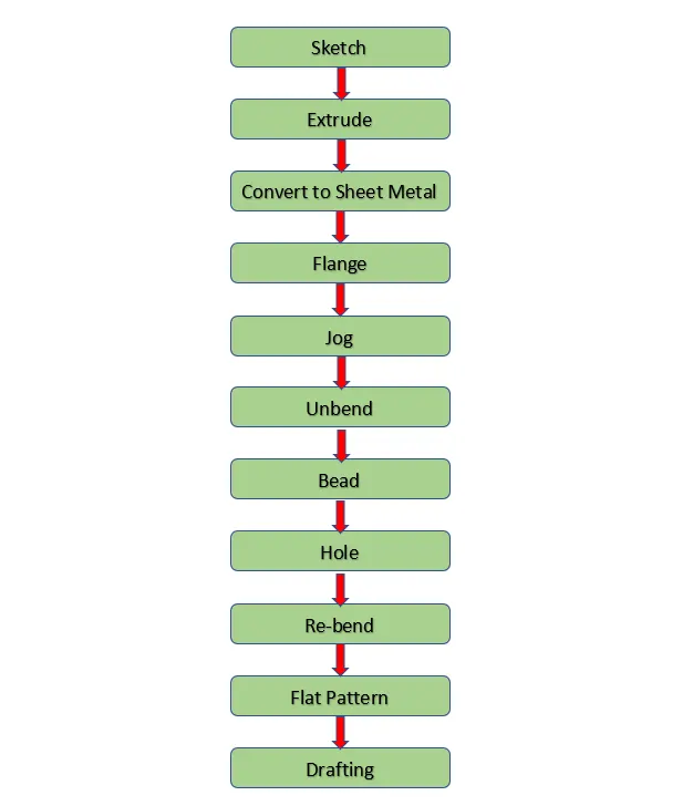
Simple and easy design methodology is followed during this project, only thing is that we have to just keep an eye on order of unbending and rebending the casing. The design methodology used for this project is summarized in below flowchart.
DESCRIPTION
- Sketch
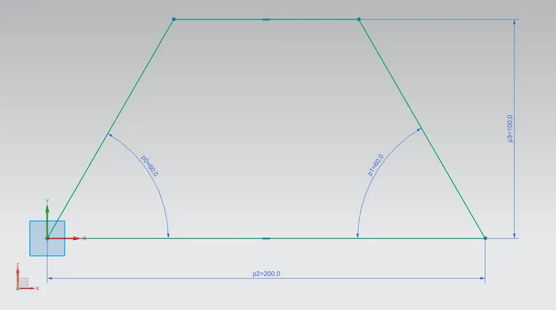
For creating any sheet metal surface, we have to first make a sketch. So i started with creating simple base sketch for creating the extrude. Other than extrude, various sketches are also made on different planes or faces for creating other different part during designing.
- Extrude
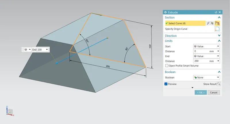
This is main feature for converting 2D sketch into 3D model. While extrusion material is added to sketch.
- Convert to Sheet Metal
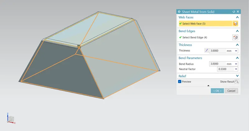
This feature is used to create a sheet metal model from generic solid body by ripping edges, cleaning up geometry and converting to a sheet metal body. First, we have to select five faces out of six in select web face section and then select four edges in select bends edges and create the sheet metal body.
- Flange
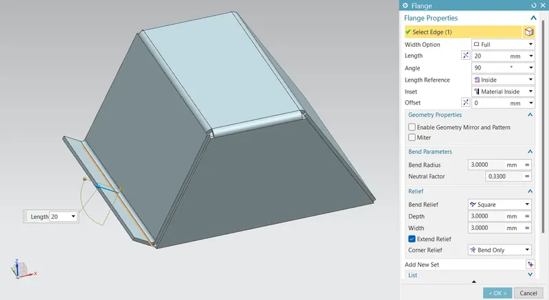
Flange is used to add extra material to the existing edge at any angle and of any size. For this project of odd shapes enclosure design., we added full flange having parameter of 20mm length with material inside the reference edge.
- Jog
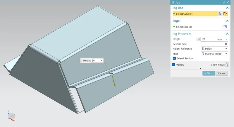
Jog feature is used to modify the model by lifting material on one side of the line, thus adding a flange between two sides. First we had created a line sketch for jog line and then create a jog having a height of 20 mm.
- Unbend
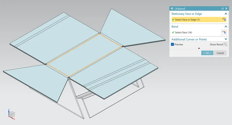
Unbend feature is one of the most powerful feature in NX. In industry we have to mark all the markings and sketch on flat sheet metal before it went to actual operations, so this unbend feature allow us to do that activity in Siemens NX software. For this project of odd shaped enclosure design, we used this feature by seleecting upper facee as stationary face.
- Bead
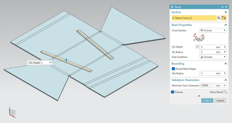
Bead is similar feature like dimple, the only difference is that by using dimple we lift an area while in bead we lift the contour of the sketch. It also added to strengthen the component, For this project, two beads are applied in the position as shown in the image below.
- Hole
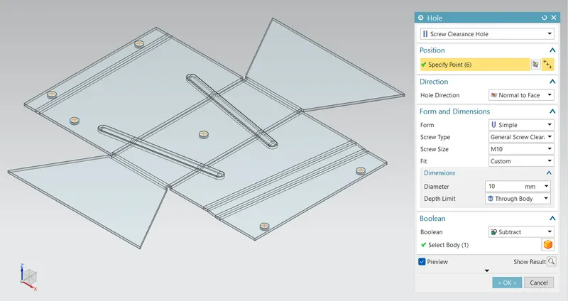
Hole feature is used to generate hole with definite parameter on sheet metal in Siemens NX. We can create different types of holes using the festure, in this project i mainly used simple screw clearance hole. We first sketch 6 location points with and then hole feature is applied to all six points.
- Rebend
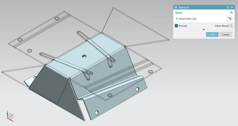
Rebent feature iss used to restor the unbend feature to its previous bent state along with any feature added after the unbend feature. This is done by using rebend and selecting all the bends carefully in order they unbend.
- Flat Pattern
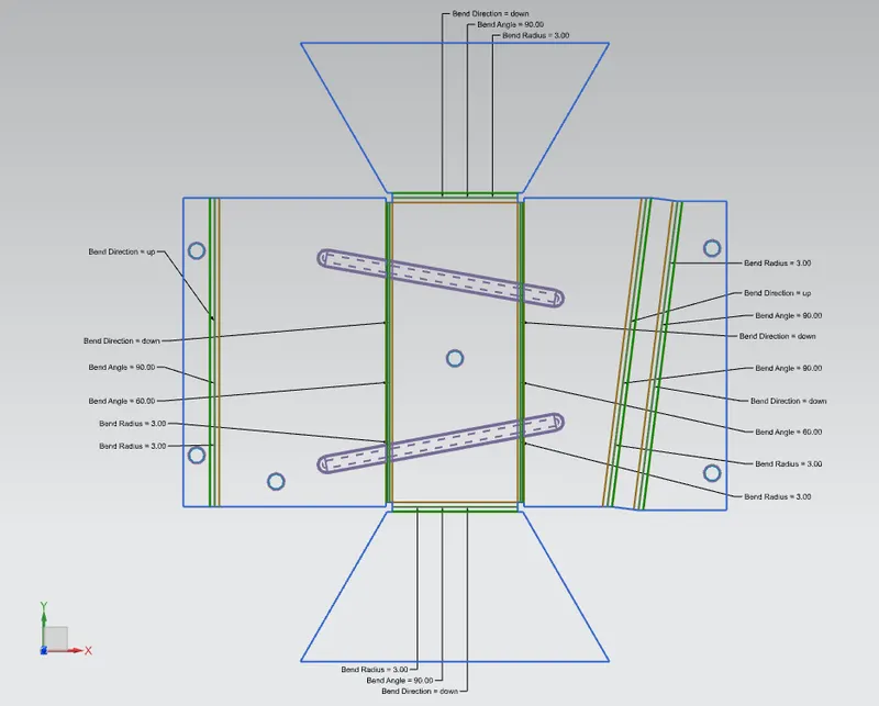
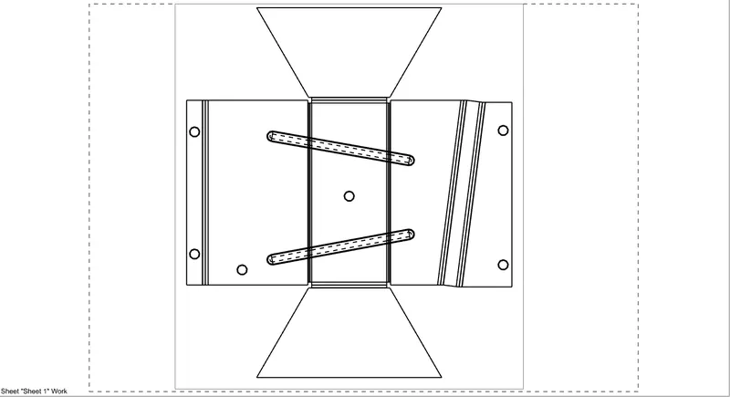
Flat pattern feature allows us to convert 3D sheet metal component into 2D form in Siemens NX software. By using the flat pattern we can easily avoid error like interference or collision.
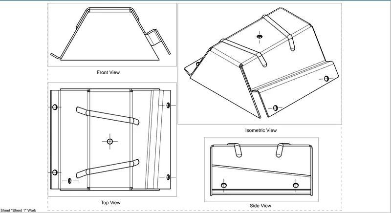
STANDARED VIEWS
- Front View
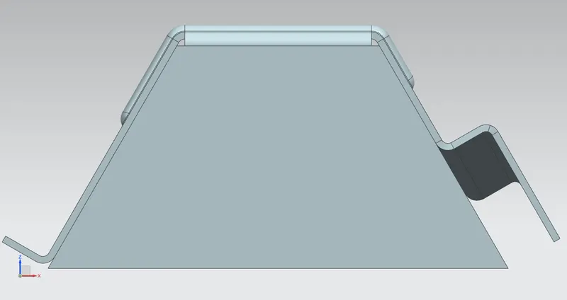
- Side View (Left)
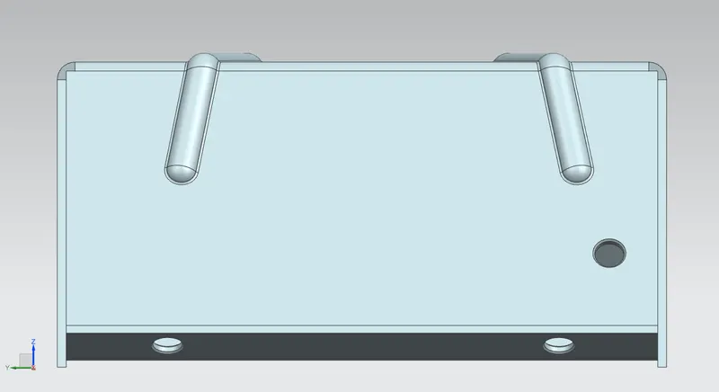
- Side View (Right)
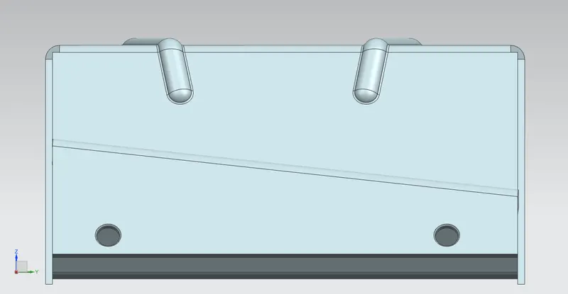
- Top View
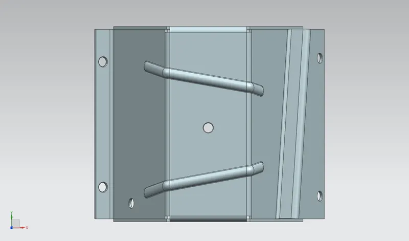
- Isometric View
DRAWING SHEET IMAGES
After designing 3D model for further process of manufacturing we have to convert the entire sheet metal component into 2D form for easy interpretation. For this project of add shaped enclosure design a drawing is created out of the flat pattern in 2:1 scale in A4 size sheet.
- Flat Pattern
- Standard DViews
CONCLUSION
Accurate modelling as per the guidelines was done for the odd shaped enclosure using thee software Siemens NX. Proper understanding about the sheet metal application tools/commands has been achieved.