Advanced Sheet Metal Design Using NX Cad Challenge_5_Odd Shaped Enclosure
Title
Creating enclosures with odd shapes or angles using NX sheet metal
Objectives
To design a sheet metal part for odd shapes using Siemens NX sheet metal Application.
Introduction
Siemens NX software is a flexible and powerful integrated solution that helps us deliver better products faster and more efficiently. It is used for: Design (parametric and direct solid/surface modelling), Engineering analysis (static; dynamic; electro-magnetic; thermal, using the finite element method; and fluid, using the finite volume method) and Manufacturing finished design by using included machining modules. Here we design a sheet metal part for odd shapes and angles.
Design methodology
Description
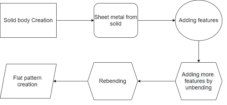
The tools used while the procedure is explained below. When we create a new sketch, a dialog box pop-ups asking us to define the Sketch Plane. The screen will display the sketch options. We can choose the Sketch Plane, direction of sketching and type of plane for sketching. When we create a sketch using the Create Sketch dialog box, we can choose the plane on which the sketch can be created by clicking on the coordinate frame as shown. This will highlight the plane we have selected. We use sketch curve tool bar sketch. This toolbar contains icons for creating the common types of curves and spline curves, editing, extending, trimming, filleting etc. Each type of curve has different methods of selection and methods of creation. Line option will selectively create only straight lines. Studio Spline can create basic spline curves with poles or through points with the desired degree of the curve. Dimensional Constraints: The degrees of freedom can be eliminated by giving dimensions with fixed entities like axes, planes, the coordinate system or any existing solid geometries created in the model. These dimensions can be linear, radial, angular etc. We can edit the dimensional values at any time during sketching by double-clicking on the dimension. Geometric Constraints: Besides the dimensional constraints, some geometric constraints can be given to eliminate the degrees of freedom. They include parallel, perpendicular, collinear, concentric, horizontal, vertical, equal length, etc. These are the basic commands used for the sketch. Now we can look into the commands used to create the features.
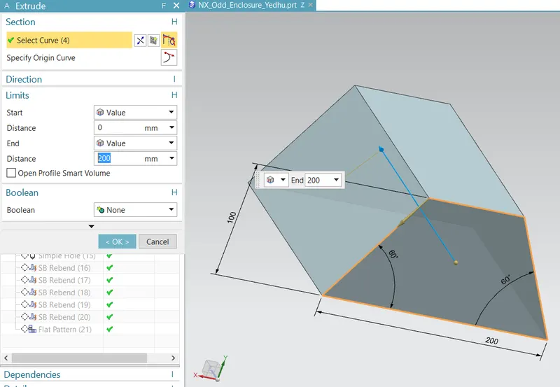
After drawing the sketch, it is made into a solid body by using extrude option. We can give thickness for the body as shown below.
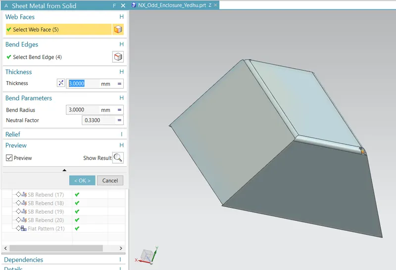
Now we can convert the created solid body into sheet metal to accomplish our objective. Sheet metal from solid option can be obtained from sheet metal application. Primarly we need to select the web face and the bend edges for the convertion. Edge selection must be done carefully, other wise sheet metal creation will show us some errors.
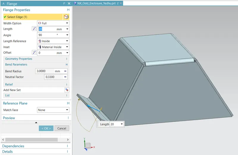
We can add some basic features as flange into the created sheetmetal as represented below.
For adding more features such as jog, additional sketches are also used.
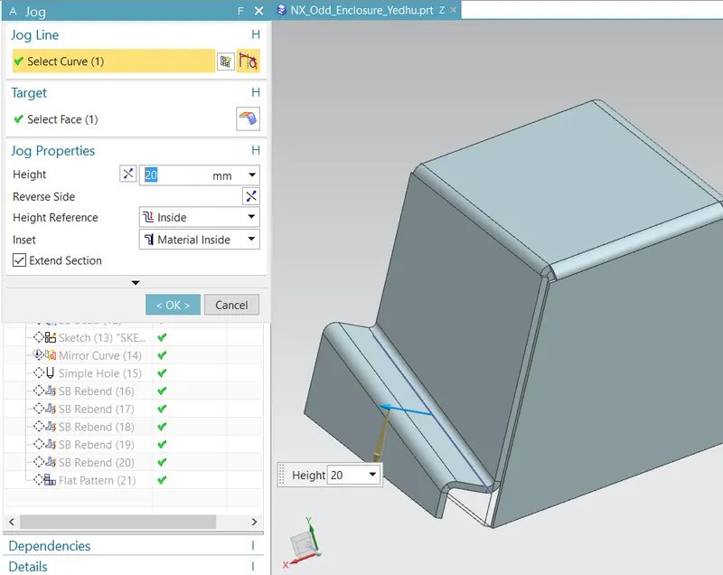
Complex features can be added into the model only after unbending it. Unbend option can be used for it.
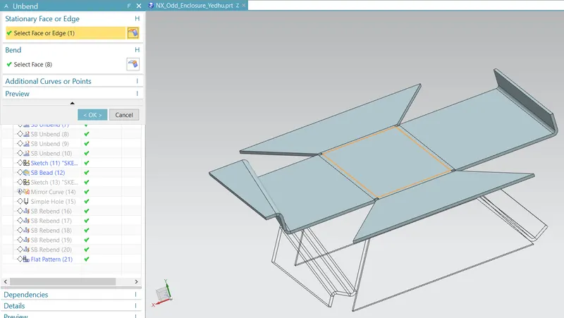
After unbending, features such as bead and holes are added using respective commands as show below.
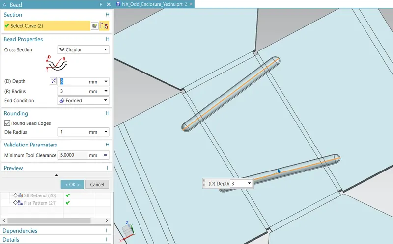
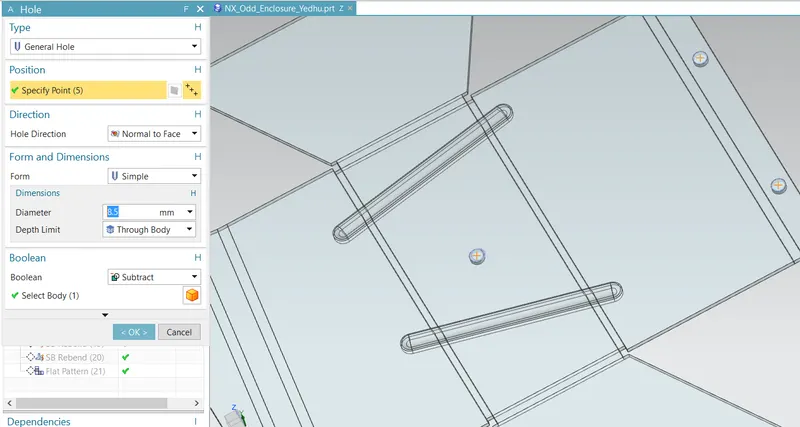
After adding all the desired features, the model is rebended back to its shape using rebend option.
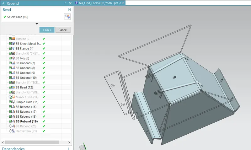
Now, the final images of the model is obtained and it is represented below.
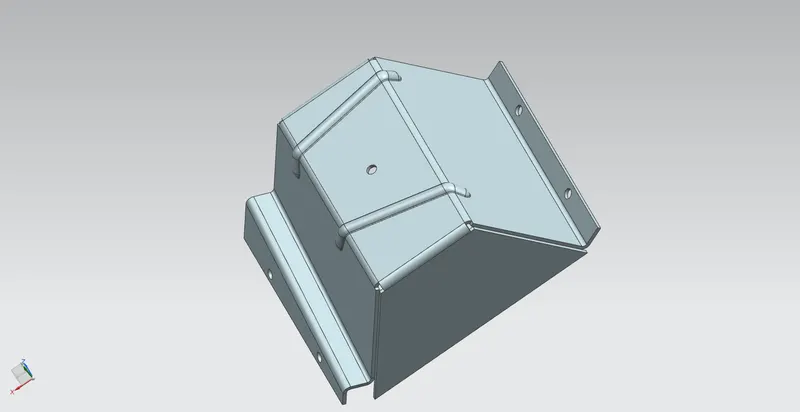
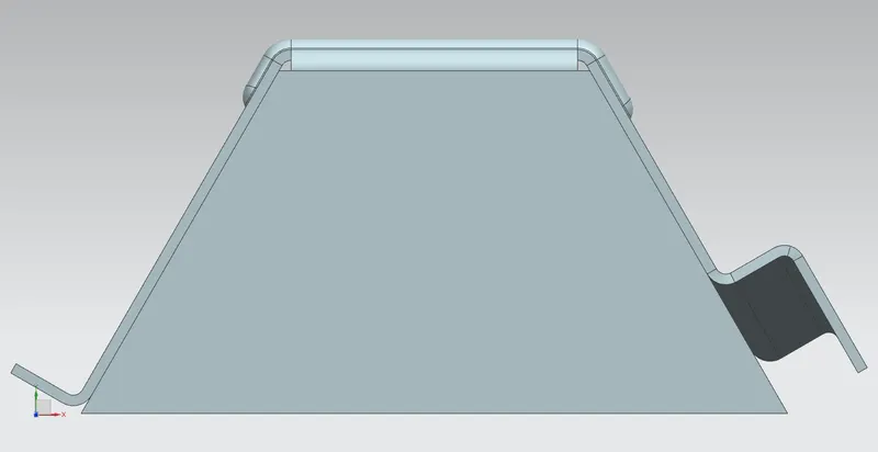
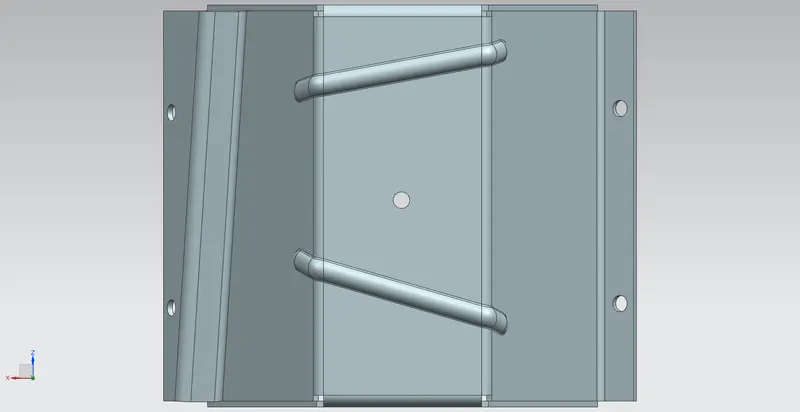
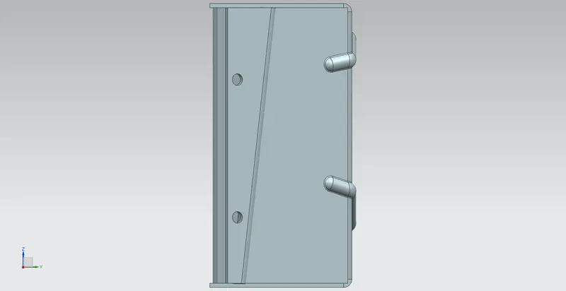
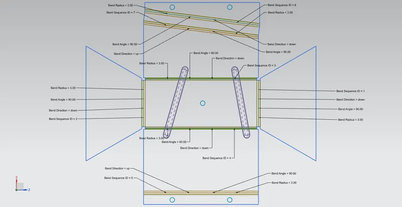
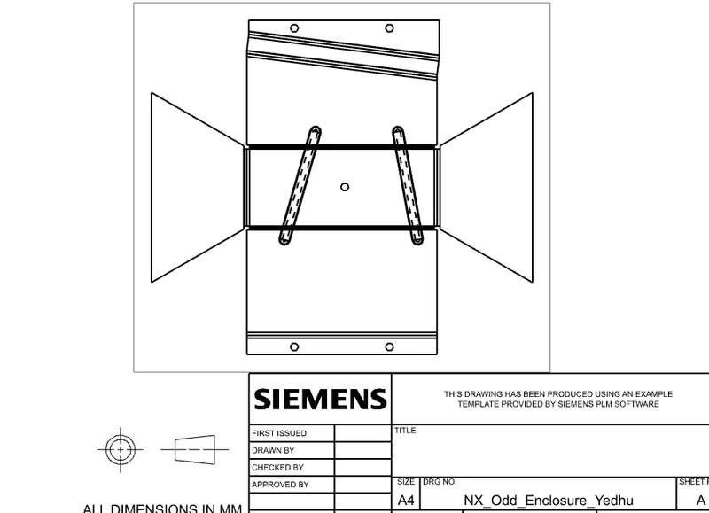
We can add flat pattern view for better understanding and the created pattern view can be drafted for future use. They are given below.
Conclusion
Sheet metal part for odd shape was modelled using Siemens NX sheet metal application.