Sheet Metal Design Odd Shaped Enclosure
Odd Enclosures- NX CAD
Objective: To understand the workflow for designing the odd Sheet Metal Components using Siemens NX Sheet Metal application.
Introduction: Sheet metal components are the parts formed by punching, stamping, cutting and bending. In this project we are going to understand the design procedure for odd Sheet metal components using NX CAD. In this project we would get introduced to the advanced commands of Sheet metal application of the Siemens NX CAD software.
Design Methodology:
Features and Tools Used:
- Direct Sketch: We use its tools to create a base sketch. (for eg: Rectangle, Circle, Line, etc.)
- TAB feature: We extrude the base sketch using the TAB feature from the toolbar.
- Flange feature: We provide flanges to the extruded tab using the FLANGE feature, from this toolbar.
- Jog: We create a flange with help of a guide curve.
- Corner: After creating the flanges we eliminate the corners using the CLOSED CORNER feature in order to ease the manufacturing process.
- Dimple and Beads: We provide the necessary slot using the DIMPLE command and BEAD COMMAND.
- Hole: The command is used to create a hole easily with help of a reference point. All the standard dimensions of the hole are already loaded into the NX library.
- Cutout: Using the NORMAL CUTOUT tool we remove the material from the required location.
- Sheet Metal From Solid: This command allows us to create Sheet Metal From an existing Solid Body.
Procedure:
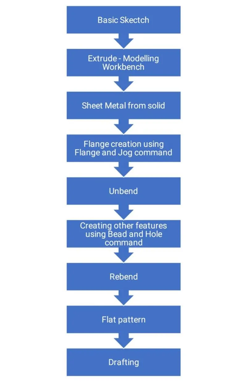
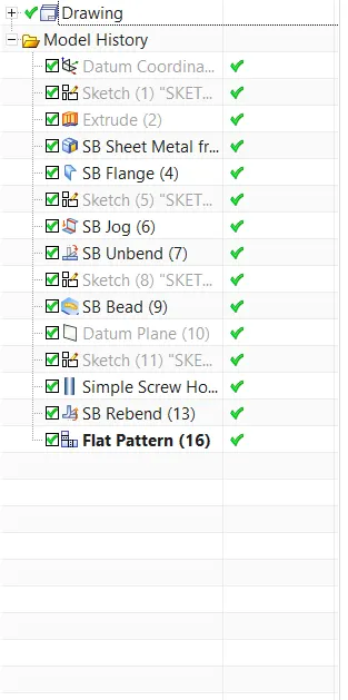
- First we create a solid body from a basic sketch using the EXTRUDE command from the modelling workbench.
- After that we use the SHEET METAL FROM SOLID command in the Sheet Metal workbench to create the base of the sheet metal component which is wrapped around the solid.
- Further we hide the solid body and continue to work on the flanges using FLANGE and JOG command.
- Next we unbend the sheet metal created and design the necessary features on the surface with help of BEAD and HOLE command.
- Lastly we rebend the component to generate our final part.
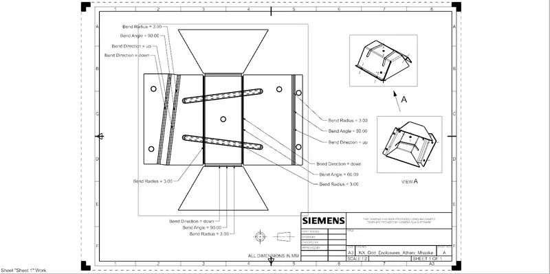
- For Drafting we create a FLAT PATTERN VIEW in order to showcase the dimensions clearly.
Component Formed:
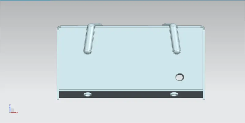
Front View:
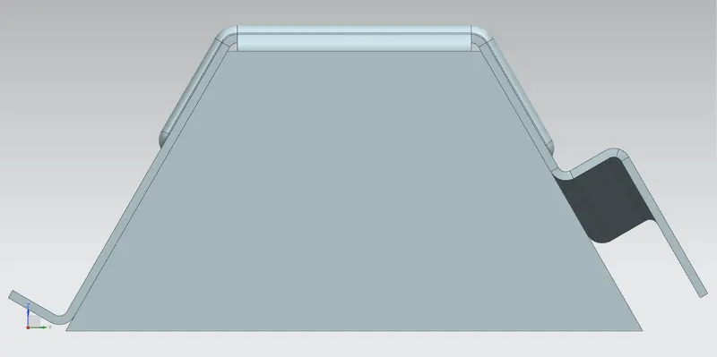
Side View:
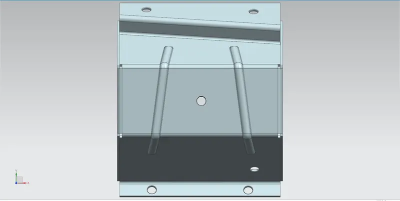
Top View:
Drafting:
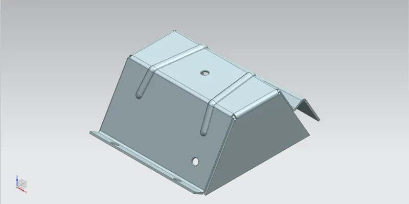
Isometric View:
Tree Structure:
Conclusion:
We have successfully understood the workflow for designing the odd enclosures for sheet metal components using Siemens NX Sheet Metal Application.