Advanced Sheet Metal Design Using NX Cad Challenge_3_Dimple Using solid punch
Dimple Using Solid Punch - NX CAD
Objective:
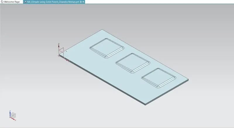
Dimple Using Solid Punch in Sheet Metal Part. Dimple is used to give more strength to thr part. The flat portion of the part posses less strength & rigitity. So, there are high chances of failure in the part. The Dimple adds strength & rigidity to the part also reduces the chances of failure.
Explanation of Punch & Die
Punch:
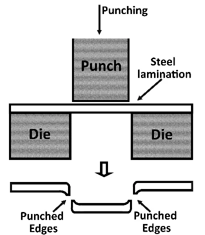
Punching is a forming process that uses a punch press to force a tool, called a punch, through the workpiece to create a hole via shearing. Punching is applicable to a wide variety of materials that come in sheet form, including sheet metal, paper,vulcanized fiber and some forms of plastic sheet. The punch often passes through the work into a die. A scrap slug from the hole is deposited into the die in the process. Depending on the material being punched this slug may be recycled and reused or discarded.
Punching is often the cheapest method for creating holes in sheet materials in medium to high production volumes. When a specially shaped punch is used to create multiple usable parts from a sheet of material the process is known as blanking. In metal forging applications the work is often punched while hot, and this is called hot punching. Slugging is the operation of punching in which the punch is stopped as soon as the metal fracture is complete and metal is not removed but held in hole.
Die:
A die is a specialized machine tool used in manufacturing industries to cut and/or form material to a desired shape or profile.Stamping dies are used with a press, as opposed to drawing dies (used in the manufacture of wire) and casting dies (used in molding) which are not. Like molds, dies are generally customized to the item they are used to create.
Products made with dies range from simple paper clips to complex pieces used in advanced technology. Continuous feed laser cutting may displace the analogous die-based process in the automotive industry among others.
Design Methodology:
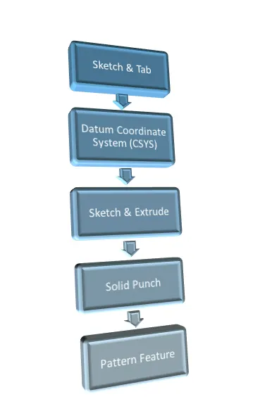
DESCRIPTION:
In the explanation process we are going to follow the steps that are mentioned in Design Flowchart.
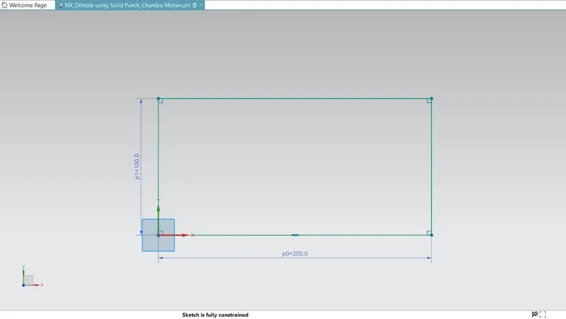
Sketch for Base Tab:
For this box, a sketch for the tab is created in the XY plane first.
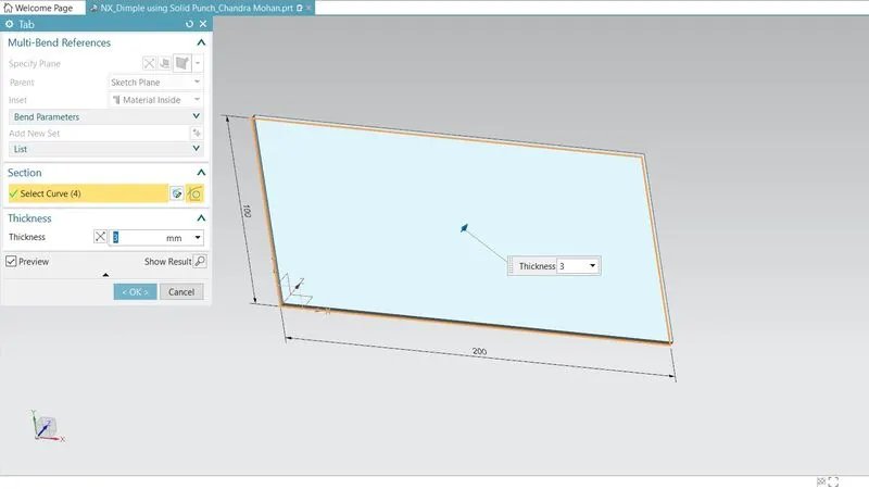
Tab Feature:
A tab is created after a sketch is created in any of the planes or datum plane created. The tab is always the parent feature for other features following it. In this casing design, the tab is created after a simple sketch in the XY plane.
Datum Coordinate System(CSYS):
With a Datum CSYS, objects are created relative to some aspect of the datum object, such as a Point, Plane, or Axis. The Datum CSYS contains 3 datum planes and 3 datum axis along with a coordinate system. When the Datum CSYS is moved, anything that referenced it will move as well.
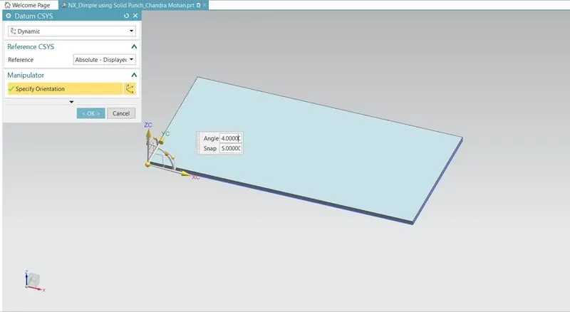
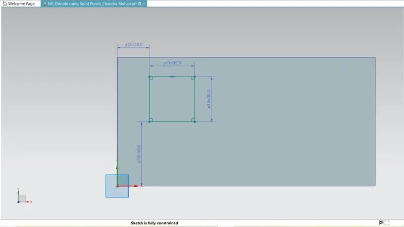
Sketch on Datum CSYS:
With the help of the new coordinate system, we are creating a punch tool on the Base of Sheet metal. Now sketch the required shape.
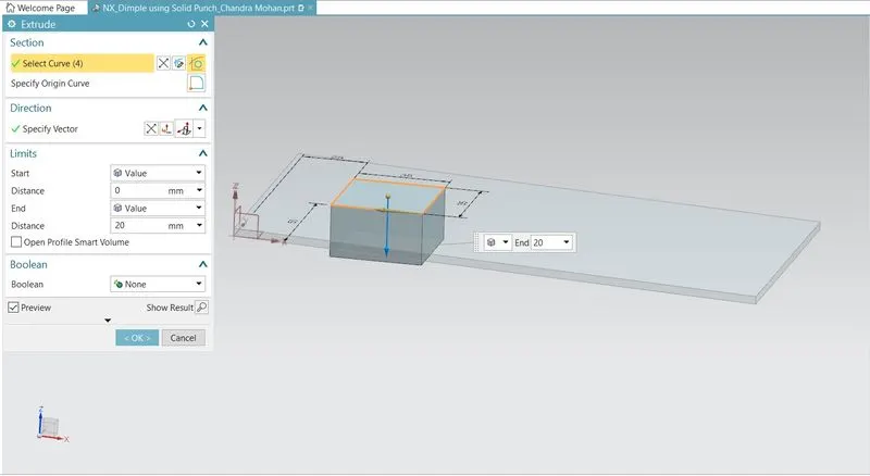
Extrude Feature:
Now extrude the sketch that are drawn in the CSYS. Specify the required dimensions to downside extrude.
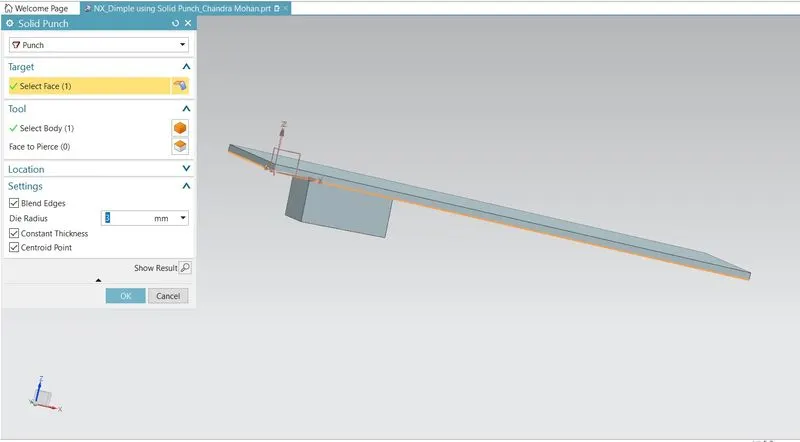
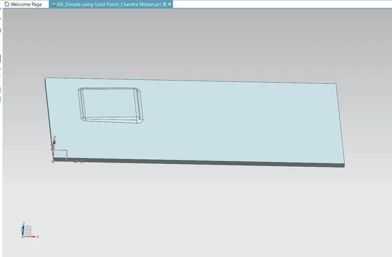
Solid Punch:
An Solid punch is a tool used to produce a dimple in a workpiece (for example, a piece of metal). ... When pressed against the workpiece, it stores energy in a spring, eventually releasing it as an impulse that drives the punch, producing the dimple.
Before After
Pattern Feature:
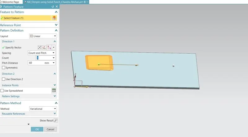
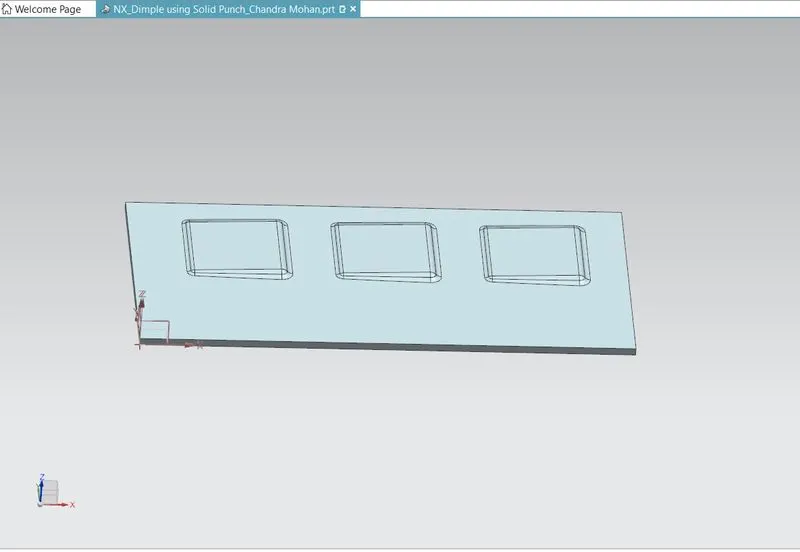
The pattern feature is an feature that allows the user to refer to an edge/vector to define the direction, axis, or path in Linear, Bilinear, circular, edge, and sketch path patterns.
A pattern consists of multiple instances of a feature. Select a pattern type and define dimensions, placement points, or a fill area and shape to place the pattern members. The result of the operation is a feature pattern.
Before After
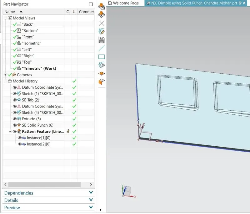
Feature Tree:
Dimple Using Solid Punch
(MODEL VIEWS)
Top View
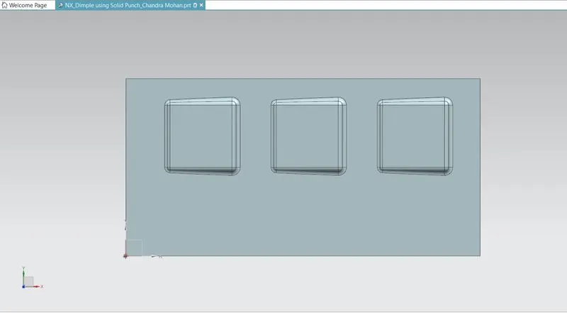
Bottom View
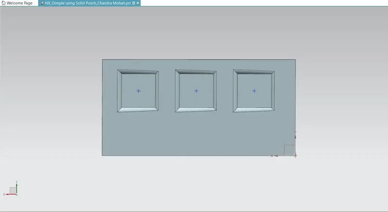
Front View
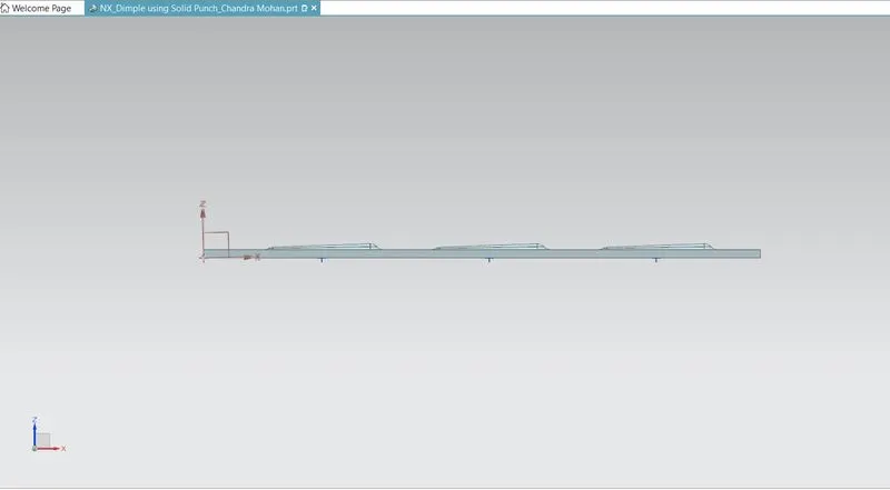
Side View
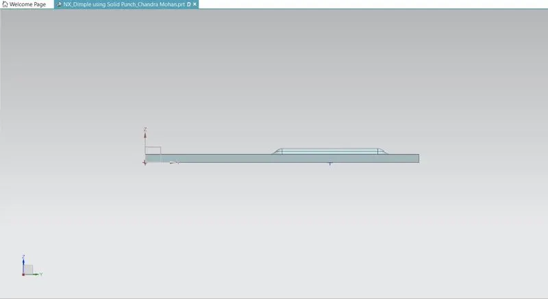
Isometric View
Conclusion:
Dimple at Sheet metal is designed successfully using Solid Punch Feature in NX CAD.