Advanced Sheet Metal Design Using NX Cad Challenge_2_Box Assembly
BOX ASSEMBLY DESIGN USING NX CAD APPLICATION
OBJECTIVES:
The objective of this project is to understand the NX Cad interface and basic sheet metal features by working on a design for box assembly.
INTRODUCTION:
Sheet metal is metal formed by an industrial process into thin, flat pieces. Sheet metals can be bent and cut into a variety of shapes. The thickness of sheet metal is known as a gauge. Sheet metal application is used widely in
- Aircraft bodies
- Automobiles
- Utensils used for domestic purpose
- Beverage cans
NX Cad helps to design the sheet metal parts using basic features such as flanges, tabs, and jogs. We can also close corners, and create cut-outs and stiffening features. Using NX we can convert the solid models into sheet metal parts. Modeling and assembling commands are also available in NX cad.
In this project, we design a box with an outer cover and hinge. It can be used for storing. Based on the weight carrying capacity and conditions the material keeps on changing.
DESIGN METHODOLOGY:
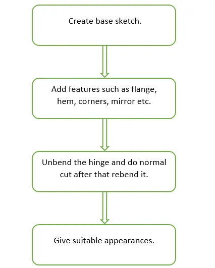
SHEET METAL MODELLING:
Features and Tools:
- Tab: This command is used to create a base feature. Sketch along with the thickness gives tab. All further features are added to the tab.
- Flange: This feature used to add a flat flange at an angle to the face and add a bend between two.
- Break Corners: This feature makes sharp edges to smooth round shape or to chamfer shape.
- Closed Corner: This feature is used to close the corners where two flanges meet.
- Dimple: Use dimple command to lift an area of the model inside a sketch that stimulates a stamping tool.
- Beads: This command is also used to lift material along with the contour sketch that stimulates the stamping tool. In beads the cross-section can be changed.
- Hem: Folding the edge onto itself for increasing the edge stiffness. Always created as a secondary feature.
- Unbend: This feature helps to unbend the bent shapes to a flat pattern. In sheet metal the other features like cut-outs and holes needed to be created over the flat configuration. So that feature applied will be normal to a flat surface.
- Rebend: This command helps to rebend the previously unbent sheet and have a component in its original form.
- Normal Cut-Out: It helps to cut material by projecting a sketch onto the model, cutting perpendicular to the face.
- Datum: Datum is the plane for starting the sketch.
- Mirror: Mirror is used to mirror a body or feature about a plane or face.
- Unite: This feature helps to combine the body into a single model.
Procedure:
- Draw a rectangular tab on XY plane with a thickness of 1mm.
- Use the flange command and select the shorter edges of the rectangle. Flange length is given as 200.
- Select the right view. Select both the edges of the flanges created earlier and create another flange with 70mm length.
- Using a closed corner, close the gaps on the corner.
- Create a small flange without any bend radius on the flange that created previously.
- Select the edge of a small flange and create another flange which is bent outside with a length of 6.5mm.
- Create an open hem with 0.5mm bend radius at the previous flange now it looks like an interlock and the stiffness of a material is increased.
- Mirror the body with respect to the YZ plane. Then using the unite feature make it into a single body.
- Select the outer side of the box and sketch X shape with 10mm fillet around the corners. Then create a dimple using the sketch.
- Using mirror feature mirror the dimple with respect to XZ plane.
- Select the bottom surface and sketch a rectangular shape and fillet the corners with a 10mm radius. Then create the dimple.
- Unbend and rebend the model.
- On the bottom surface create a circular bead of 15mm. Then mirror the feature to the 4 corners.
- Create a closed hem on the top 3 edges of the flange.
- Create a new plane with respect to the XY plane at a distance of 203mm.
- Design a lid on the new plane, using tab.
- Give a 3mm flange to the long edge.
- For creating the hinge select the right side of the body, and sketch a rectangle and give the tab feature.
- At the left corner of the new tab create a corner brake with a radius of 10mm.
- Create a flange by selecting the upper edge of the new tab and give an angle of 40degree with a 4mm length. Create a new flange again by selecting the edges of the previously created flange and give a 40degree angle and 4mm length.
- Create an open hem at the edge of the previous flange. Give 5mm bend radius and 325 sweep angle.
- Unbend the hinge.
- Select the face and sketch 2 rectangles with given dimensions. This sketch is used for the normal cut-out feature.
- Rebend the new body and mirror this body with respect to the XZ plane.
- Select the top of the lid and create a new sketch. Draw a rectangle and add thickness using a tab.
- Apply break corners to the bottom 2 corners.
- Apply flange at the top edge with 13mm length and an angle of 39degree.
- Add open hem to the previous flange and give 5mm length and 325 sweep angle.
- Unbend the upper hinge and perform a normal cut as done earlier.
- Give appropriate appearance.
Result:
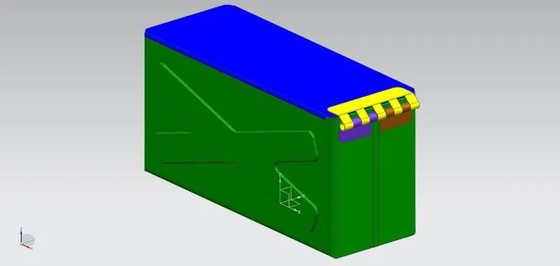
FIG: Isometric View
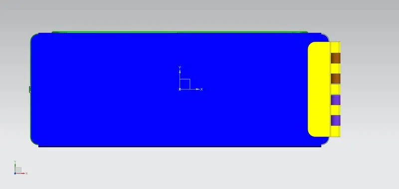
FIG: Top View
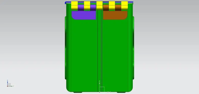
FIG: Side View
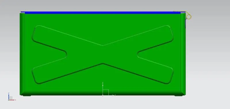
FIG: Front View
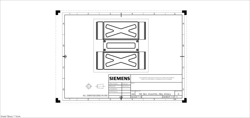
FIG: Drawing Sheet
CONCLUSION:
The sheet metal Box Assembly is designed and drafted successfully in NX cad application. From this project we got a basic approach to sheet metal modeling and utilization of basic commands.