Advanced Sheet Metal Design Using NX Cad Challenge_2_Box Assembly
BOX ASSEMBLY- ADVANCED SHEET METAL DESIGN
OBJECTIVE:
To design a box assembly using NX CAD -sheet metal workbench.
INTRODUCTION:
In this project we are gonna design a sheet metal casing with NX CAD on sheet metal workbench. NX is a advanced CAD (computer aided design), CAE (computer aided engineering), CAM (computer aided manufacturing). The software performs in DESIGN (parametric and direct solid/surface modelling), Engineering analysis (static, dynamic, electro-magnetic, thermal, using the finite element method and fluid, using the finite volume method. Manufacturing finished design by using included machining modules.
DESIGN METHODOLOGY:
DESCRIPTION:
- TAB: Create a sketch for tab of 200 x 150 and thickness 1mm
- FLANGE: create flanges along the tab to create a box of length 200 and 70 at 90 degree angles
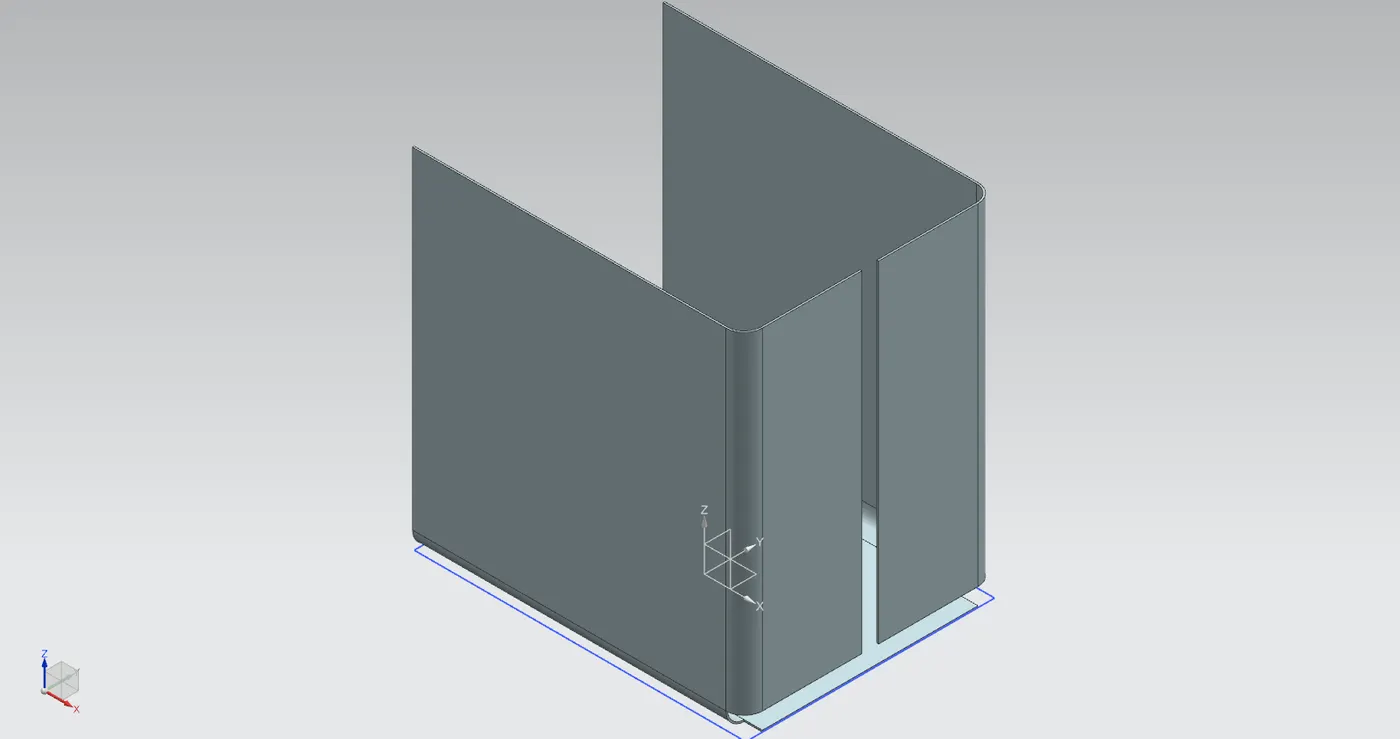
- CLOSED CORNERS: create closed corners around the flanges created to make a smooth finish.
- FLANGE & HEM FLANGE: using both the tools create a closed and strong closed sheet path for the box.
- MIRROR BODY & UNITE: create a plane to create the mirror of the body and unite both to make it as a single body.
- DIMPLE & MIRROR FEATURE: create a sketch to do a dimple lift on the body and mirror the entire feature with the parent sketch on the other side. create a another sketch at base to dimple lift.
- UNBEND & REBEND: unbend all the bends of the box and rebend it with the same progressive order.
- BEAD & MIRROR FEATURE: create beads at the bottom of the base tab using sketch and bead feature.
- HEM FLANGE: create hem flanges on top of the body facing outside.
- DATUM PLANE & TAB & FLANGE: create a datum plane above the base tab and draw a sketch of the same body as top cover for the box. create flanges at the tab created at the ends for the smoothed edges.
- TAB & BREAK CORNER: create a tab using sketch at the side of the box and break the corners for smooth edges.
- FLANGE & HEM FLANGE: create angled flanges and a open loop hem flange on the tab created at side of the box.
- UNBEND & NORMAL CUTOUT & REBEND & MIRROR BODY: Unbend all the flanges and hem flange and create a sketch for a normal cut sections using NORMAL CUTOUT and rebend back all of them in the reverse progressive order of unbend. now mirror the body created using MIRROR BODY.
- TAB & BREAK CORNER & FLANGE & HEM FLANGE: Create a tab on the top of the cover tab and using break corner to smooth its edges. create flanges of angles and create a open loop hem flange at last.
- UNBEND & NORMAL CUTOUT & REBEND: Unbend the flanges created and create sketch for cut sections to cutout using NORMAL CUTOUT and rebend it again.
MODEL VIEWS:
1. FRONT VIEW
2. SIDE VIEW
3. ISOMETRIC VIEW
4. TOP VIEW
DRAWING SHEET:
CONCLUSION:
From the NX CAD by the tools and features of the sheet metal workbench like SKETCH, TAB, NORMAL CUTOUT, CLOSED CORNERS, FLANGE, HEM FLANGE, DATUM PLANE, MIRROR BODY, UNITE, DIMPLE, UNBEND, REBEND, BEAD, MIRROR FEATURE, BREAK CORNER etc we conclude the BOX ASSEMBLY OF SHEET METAL.