Advanced Sheet Metal Design Using NX Cad Challenge_2_Box Assembly
TITLE :
Sheet Metal design using NX CAD
OBJECTIVE :
Development of Box Assembly using NX CAD
INTRODUCTION :
Sheet metal is a flat, thin piece of metal that is widely used in manufacturing, construction, automotive, and many other industries. It is known for its versatility, durability, and ability to be easily shaped and formed into various products. Sheet metal thickness is usually measured in gauges. The gauge number indicates the thickness of the metal; the higher the gauge number, the thinner the sheet. For example, a 16-gauge steel sheet is thicker than a 20-gauge steel sheet. Thickness can also be measured in millimeters or inches. Sheet metal can be classified as foil, sheets and plates depending upon the thickness, where foil lesse than the 0.15mm, sheets is lesser than 6.35mm and thickness greater than 6.35mm is called as plates. sheet metal commonly come with Hot rolled steel and cold rolled steel.
HOT ROLLED STEEL : This steel is produced through the process of rolling the steel at a high temperature, typically above the recrystallization temperature of the material (usually above 1,000°F or 538°C). After rolling, the steel is cooled in the open air. This cooling process allows the steel to shrink slightly, which can lead to some variation in its dimensions and a rough, scaly surface finish. Hot rolled steel typically has a rough, scaly finish due to oxidation during the heating process. The surface may appear bluish or have a dark gray scale, known as mill scale.
COLD ROLLED STEEL : This steel that has been further processed after the initial hot rolling. It is rolled at or near room temperature to achieve more precise dimensions and a smoother surface finish. It has a much smoother surface finish than hot rolled steel. It is often free of scale and has a more uniform appearance.
DESIGN METHODOLGY :
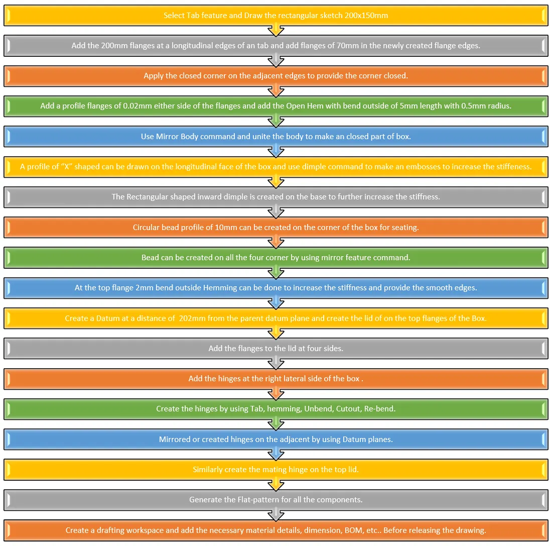
DESCRIPTION :
what is Assembly ?
Model Assembly is the process of creating a digital representation of a product by combining multiple individual components into a larger, complete structure. This is essential for visualizing how different parts fit and interact with each other, ensuring that the final product functions as intended. This represent the real time product with the assembly sequence. There are two main methods for assembly development single-part file assembly and multi-file assembly. Each method has different approaches for managing parts and components within an assembly. Both Methods havee their own Pros and cons.
Single Part file Assembly :
In this Method all the components are exist as Bodies in one part file. The bodies are have the same origin space so there is no need of any additional constrains or mates. All the components are relative to each other. The main drawback by this method is the resuability and the components cannot be easily used in another product and the ownership of the development can be depend upon single designer.
Multiple Part file Assembly :
In a multi-file assembly, each component of the assembly is created as a separate part file. These part files are then inserted into an assembly file, where their relationships and positions are defined using constraints or mates. Parts can be reused across different assemblies or projects, saving time and improving efficiency. Multiple designers can work on different components simultaneously, contributing to the overall assembly file.
In this Project we using the Single part file Assembly.
Feature Used :
- Tab : This is the basic feature used to create the base flange of the sheets. Select the plane which we need to create the surface of the sheet metal body and define the thickness, bending radius, "K" factor. Without the tab flange is created the existing other features are cannot be implement in the sheet metal part.
- Flanges : A flange is a flat or angled extension of the sheet metal, usually at the edge of the part.
- Corner treatment : After the creation of edge flanges we need to ensure the corner should be propely closed or overlapping each other and maintain the gap clearance between the two flange edges. If the relief is larger than its affect the aesthetic of the part and affect the stiffness of the component. So it very precise the provide the corner value according to the material thickenss and manufacturing process.
- Hemming : This command is applied on the edges of the flanges to fold it up to itself at and angle of 180 deg. This feature is used to increase the stiffness, aesthetic edges of the part and it is also used to hide the edge defects like burnout's and rupture surface and make the part to easily handle without any injuries to the shop man.
- Mirror Body : This feature can mirror the existing surface with respect to its Coordinate system to make a duplicate or replicate of the surface's. it will Drastically reduce the modelling time.
- Unite : This feature join two surface which will have a physical connection between the Flanges to make as a single Body or surface.
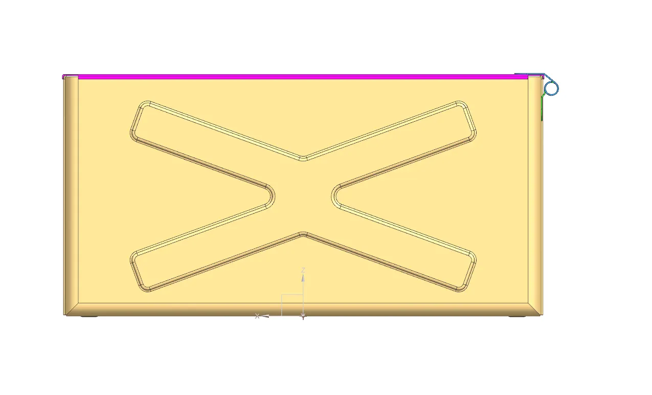
- Dimple : This is used to create the Popup surface's on th sheet metal to increase the stiffness of the product.
- Bead : This feature is similar to the dimple command but it will pop up the surface along the sketches.
- Mirror feature : It is also similar to mirror body, it will mirror the feature's according to the planes.
- Break corner : This is a handy tool make fillet on the surface edges to reduce the stress concentration.
- Unbend : It is used to unbend the edges flanges to create the cutout's are embosses where the edges can take place.
- Re-Bend : It is used to re-bend the unbended flanges to its original position's.
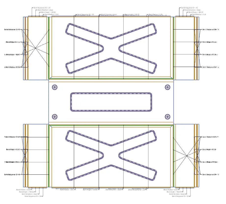
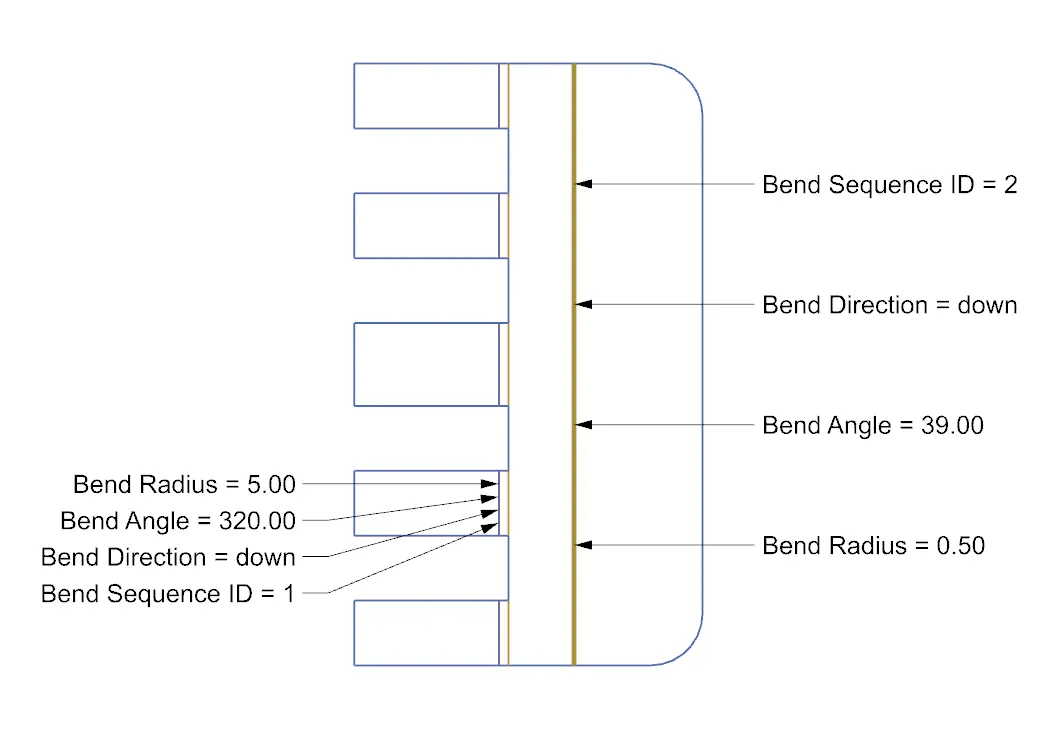
- Flattern : It is used to generate the drawing for the cutting operation and it has the bending dimension and details for V-bending operation.
Creation and Box - Assembly
Front view :
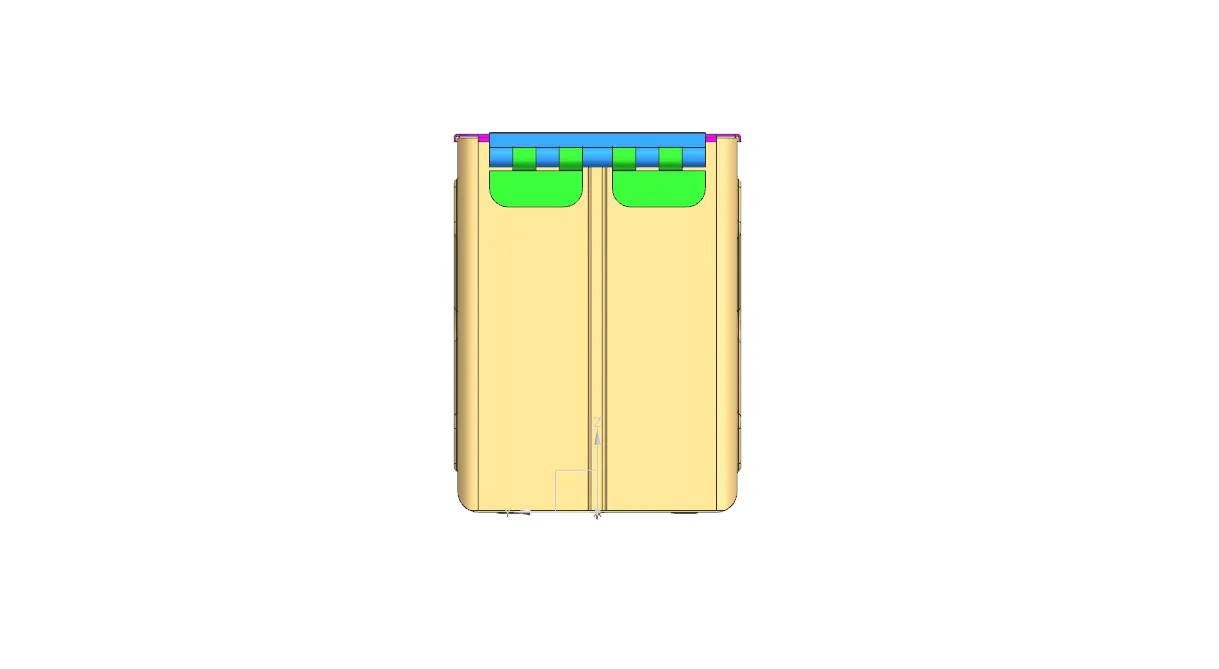
SIDE VIEW :
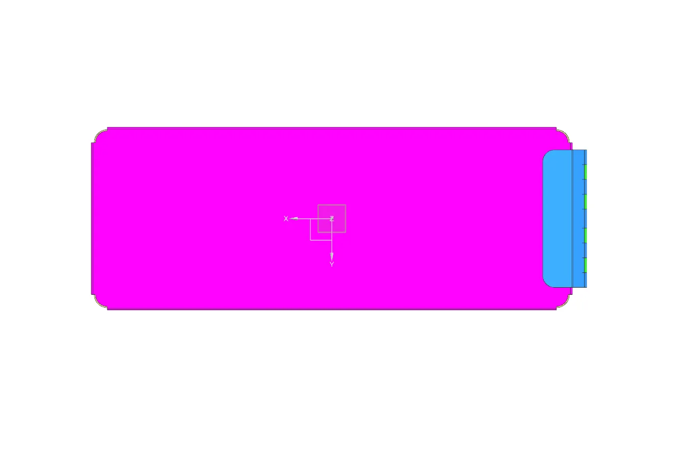
 TOP VIEW :
ISOMETRIC VIEW :
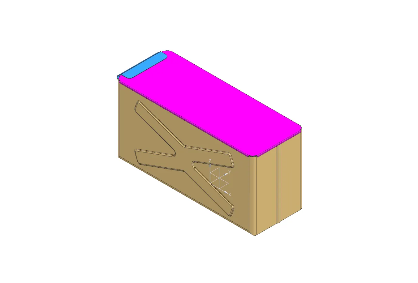
FLAT PATTERN :
Base Sheet Metal
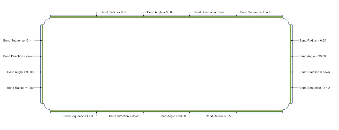
TOP LID
BASE PART HINGE
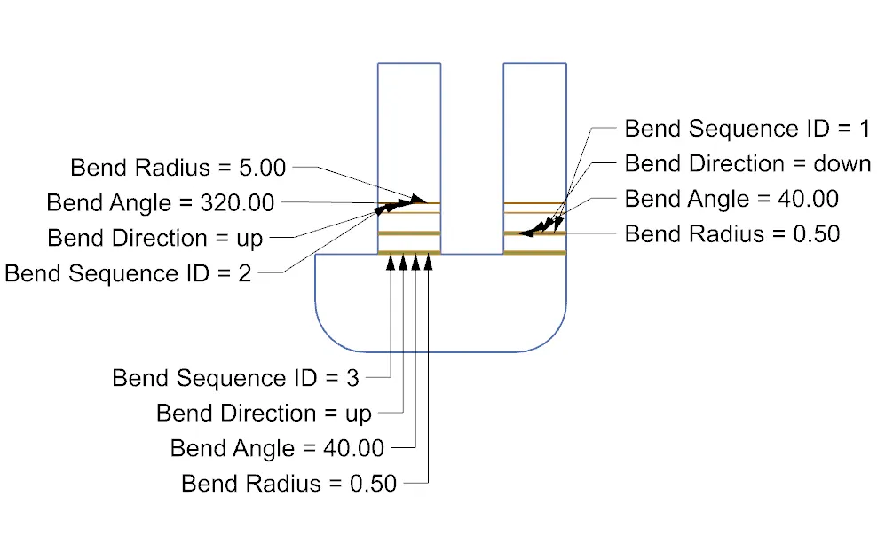
TOP LID HINGE
CONCLUSION :
From this project we have learn't about the Sheet metal feature's in NX cad and how to approach the design for simple components.