Advanced Sheet Metal Design Using NX Cad Challenge_2_Box Assembly
Advanced Sheet Metal Design using NX CAD
Challenge #2 - Box Assembly
Objective -
To design a Sheet-Metal Casing, as per the instructions provided in the PDF file using NX-CAD software. And also create a detailed drawing of the completed product.
Introduction -
Siemens NX provides a set of tools within it that allows for simple and fast design of sheet metal parts. It also incorporates material & process information and sheet metal-specific modelling features like bends, flanges, tabs, cutouts, beads, dimples, louvers, corner, edge treatments, patterns, etc. All these features eases adn enhances the design procedure & productivity.
Its also allows to convert solid models to sheet metal components, and create sheet metal parts that enclose other components. All common dimensions can be set as default for ease of work. Sheet Metal products are used in almost all industries, thus design of needed components are made easier with CAD softwares such as Siemens NX.
Design Methodology -
Description -
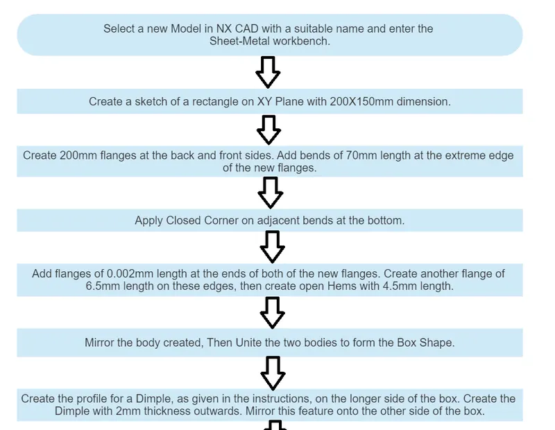
Sketch : It is basic command to draw 2D models.
Move Curve can move a created curve according to selected references by provided given distance/angle.
Mirror Curve mirrors the drawing in the sketch with respect to an axis/plane
Tab : Creates a base feature by extruding a sketch along a vector. The thickness and material data can be provided.
Flange : Adds flanges to the edges selected. Angle between main surface and length of the flange can be provided.
Closed Corner : This command is used to modify two flanges in one operation and to close the corner where the two flanges meet.
Hem Flange : It’s used to modify the edge for safety/ strength or to join 2 different sheet metals together.
Mirror Body : Mirrors the selected body with respect to a selected plane.
Unite : Joins separate bodies into one single part.
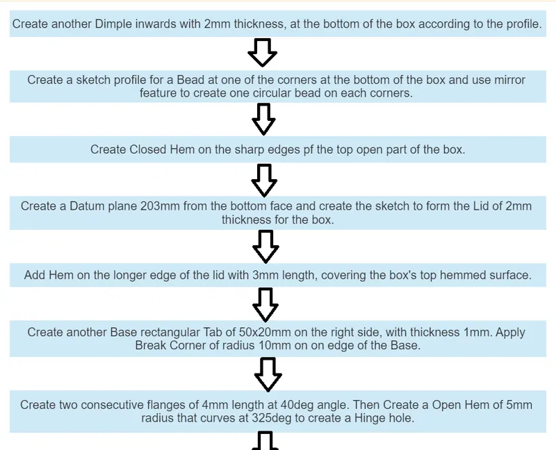
Dimple : Lifts/ creates a depression on the material along a sketch. It stimulates stamping process.
Mirror Feature : This command is used to mirror the required sketch to other side with reference to an axis.
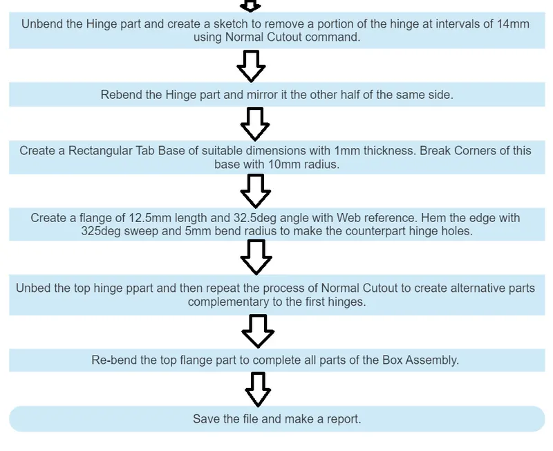
Unbend : Used to flatten the 3D sheet metal model.
Rebend : Rebends the part that was used in unbend command.
Datum Plane : Creates an offsetted plane to create sketches/ do other operartions on.
Normal Cutout : It’s used to remove unwanted material parallel to the plane of the reference sketch.
Break Corner : This command is used to round or smoothen sharp corners of a tab or flange.
Product Images -
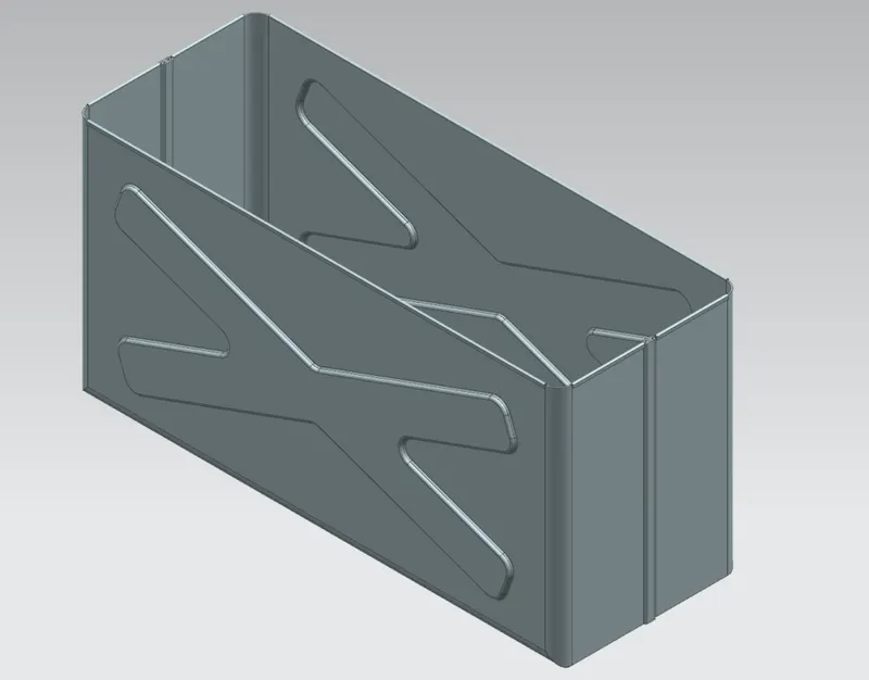
Box :
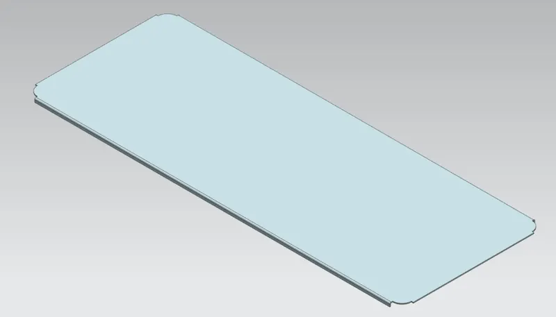
Lid :
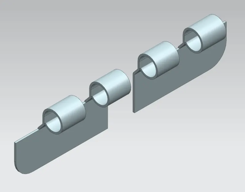
Side Hinge :
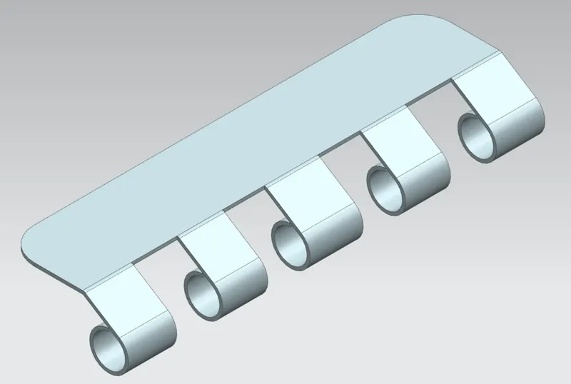
Top Hinge:
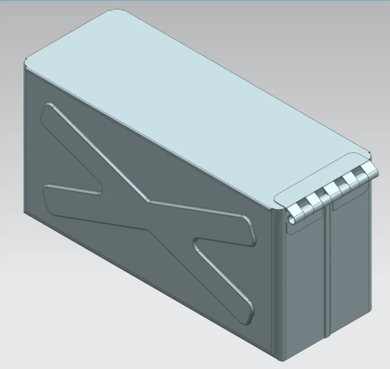
Box Assembly Isometric View :
Front View :
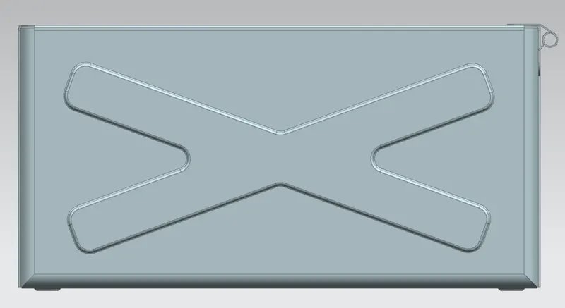
Side View (right) :
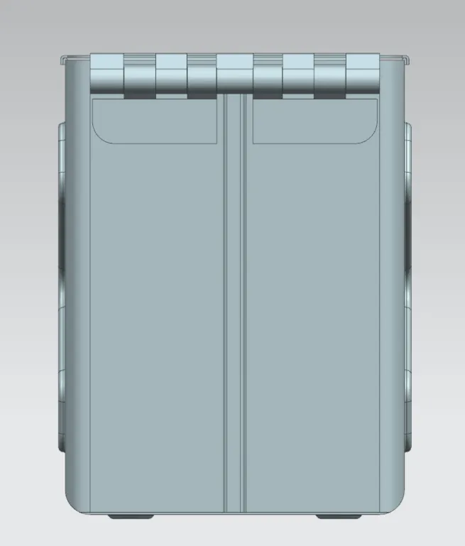
Top View :
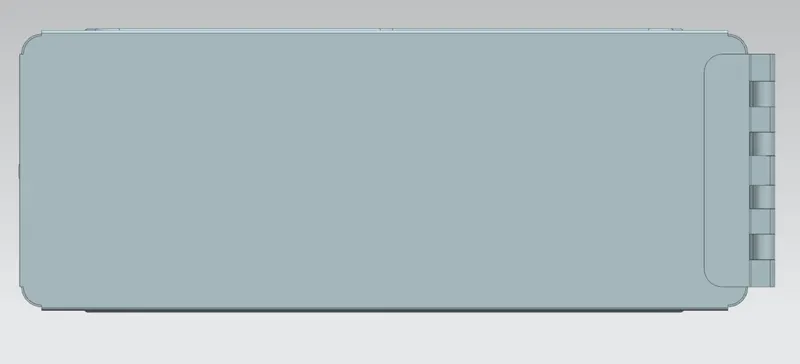
Conclusion -
The Sheet Metal Box, Lid and Hinge components of the Box Assembly is Designed using Siemens NX CAD software.