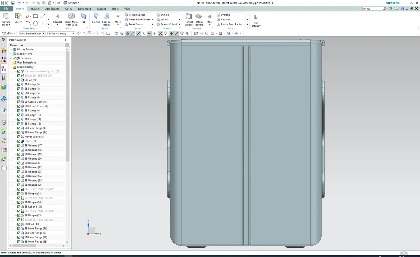
Advanced Sheet Metal Design Using NX Cad Challenge_2_Box Assembly
Sheet Metal Design of Box Assembly
Objective
This report contains a detailed explanation of Sheet Metal Design of a Box Assembly. The main objective of this course module is to learn Sheet Metal Design Assembly.
Introduction
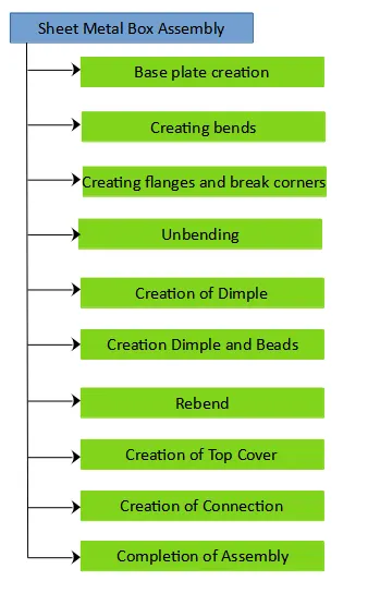
Sheet metal design is the process of making components from thin metal sheets by bending, cutting and fastening. Sheet metal design has varied application. The basics of sheet metal design are learnt and applied in creation of a Casing. The following steps were undertaking while designing the Sheet Metal Casing:
1. Creation of the base plate
2. Creation of bends, flanges and Break Corners
3. Unbend the component
4. Sketch the profile for the creation of the Dimple on the 2 opposite Faces as shown the picture
5. Sketch and create a Dimple and Bead on the center bottom face
6. Rebend the component
7. Creation of the Top cover
8. Create the connection on the lower component
9. Creation of the connection on the Top cover
Design Methodology
Features
Sketches, Tab, Bend, Flange, Break Corner, Simple Screw Hole, Dimple, Bead, Unbend, Rebend, Normal Cutout, Flat Pattern and Drafting
Description
Create a sketch on the XY plane. A symmetric rectangle of dimension 200 mm x 150 mm is drawn and a tab of thickness 1 mm is generated. Create flanges of 200 mm length and bend radius of 10 mm along the 200 mm side of the base plate. Again create flanges of length 70 mm and bend radios 10 mm on the previously generated flanges. Using Close Corner feature connect last created both flanges and the base plate. Again create small Flanges and Hem Flanges to connect the vertical open flanges to form a bend connection. Mirror the created body along the YZ plane and using Unite feature combine the bodies to make it one. Using Dimple feature create an X shaped profile on the two large vertical surfaces using the given dimensions. And on the bottom side of the box create another Dimple which is directing inwards. Create four circles on specific position on the bottom surface of the box. Create beads using these circles.
Create a plane which is parallel and is at 204 mm from the XY Plane. Making use of the outer profile of the box created, sketch the profile of the Top Cover. Using Tab feature, create the top cover of 1 mm thickness. Create flanges on the four sides of the top cover. Once the Top Cover is finished, create a Joining connection on the box and the top cover which aids in opening and closing of the box and lid assembly.
Views
1. Isometric View
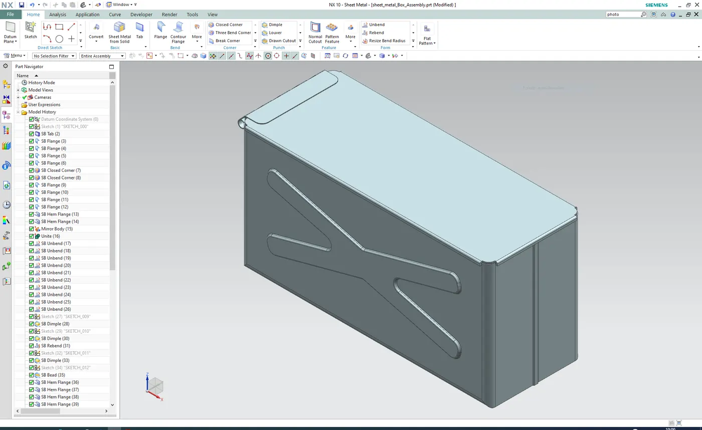
2. Top View
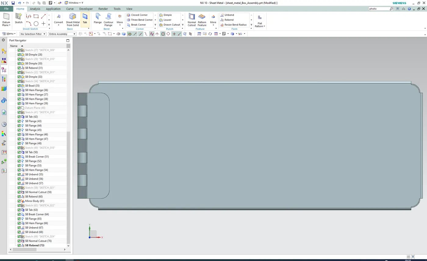
3. Front View
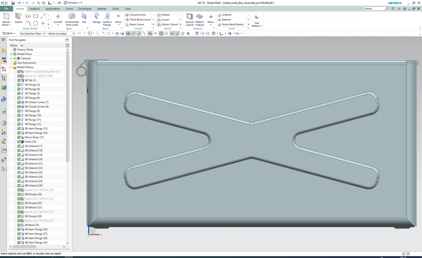
4. Left View
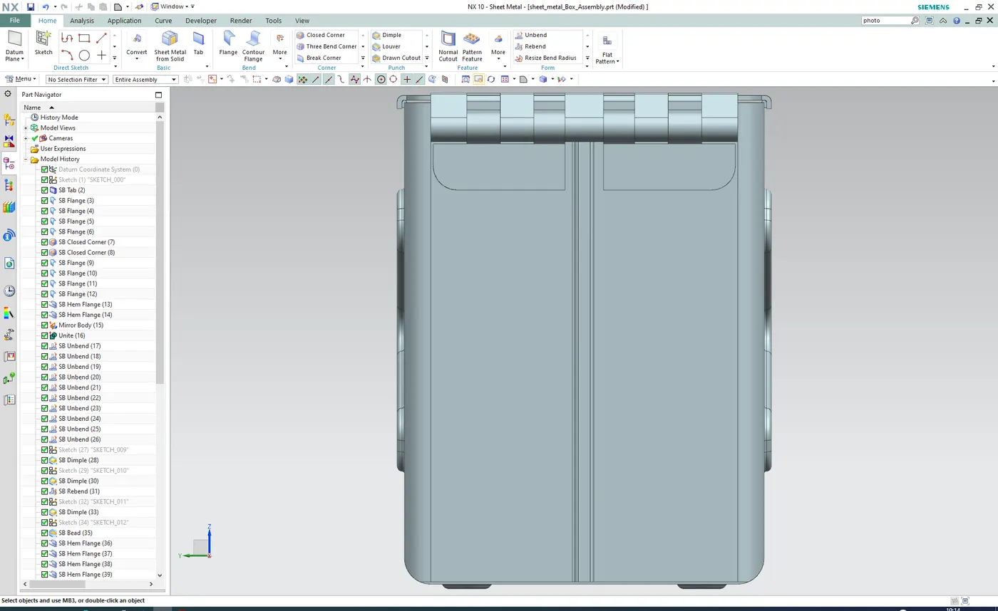
5. Right View